METIS M311 / M322 / H311 / H322 (17-pin)
Electrical Connection
12
When operating multiple devices (up to 32 are possible), each device needs to assign its own address
(directly on the device or via software SensorTools), under which it can be addressed later. For this
purpose, initially, each device must be connected individually and provided with an address (00-97). Af-
ter that, all devices can be connected.
If specific parameters for all devices should be changed simultaneously, the global address 98 is used
(there is no response from the device). If the address of a device is unknown, you have the opportunity
to address each device independently of the set address with the global address 99 (connect only one
device).
4.1.4.1 Interface Converter (Accessory)
A quick and easy way to
connect the pyrometer with
a PC is to use an interface
converter or a connecting
cable with integrated inter-
face converter (see 9.4 Ac-
cessories). Depending on
the operating system, suita-
ble drivers are installed automatically or can be found on the CD supplied with the software Sensor-
Tools in the directory Drivers FTDI_USB_COM or after installing SensorTools in the installation direc-
tory
(updated driver for Windows from the FTDI website: http://www.ftdichip.com/Drivers/VCP.htm).
To achieve the maximum transfer speed, it is absolutely necessary to change the wait time in the ad-
vanced connection settings from 16 ms to 1 ms. These settings are available in the Control Panel via
the Device Manager > Ports (COM & LPT) > USB Serial Port > Port Settings > Advanced > Wait time.
More information is available in the FTDI application note AN_107 - Advanced Driver Options.
4.1.5 Shielding
To meet the requirements for electromagnetic compatibility (EMC), only shielded cables should be
used. The shield of our connection cables is connected on the pyrometer side in the plug housing. If
faults occur during the pyrometer operation, the pyrometer should be connected to system ground. For
this, the front-side end screws have to be used, the anodized housing is not a reliable electrical connec-
tion. The shielding wire is not connected to prevent ground loops and damage caused by transient cur-
rents. When extending the cable, the screen must be extended with.
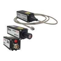
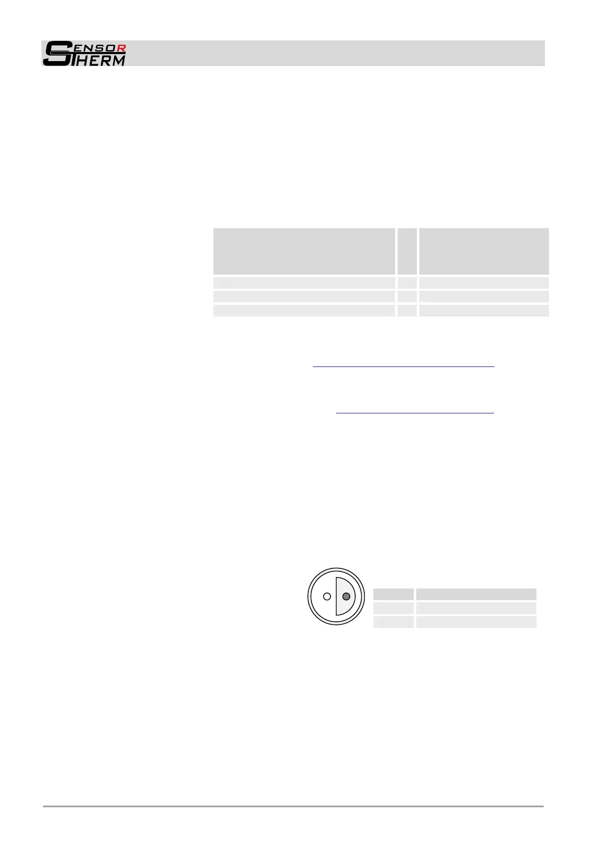
4.1.6 Camera Module
Devices with camera module as alignment are
equipped with an additional connector at the
rear (Lemo connector) for the output of the
camera signal (standard FBAS signal). Cable
see 9.4 Accessories.
cable connector: type FE.0S.302.CLAC50
Fa. Lemosa GmbH, http://www.lemo.de)
Cable colors
Metis M3 / H3
(12-pin connector)
Cable colors
interface converter
RS232USB (TxD / RxD)
RS485USB (A‾ / B
+
)
White-pink or brown-pink (DGND)
White-yellow or white-grey (B
+
/ RxD)
Brown-yellow or brown-grea (A‾ / TxD)
 Loading...