Signal Connections 11
Illustration 3
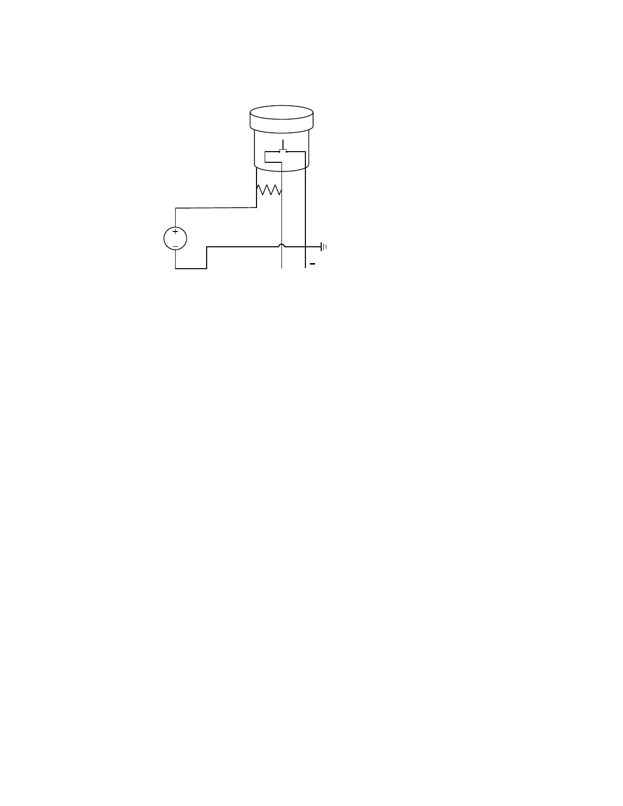
Illustration 3 is used for instruments without internal pull-up resistors and without
optical isolators internal to their inputs. Ground is common for both the OMNI register
and instrument. When the OMNI’s MOSFET is open (not conductive), nearly the full
voltage supplied to the OMNI will occur at the instrument’s input. It must be able to
withstand this voltage (24 VDC in Illustration 3).
*In case the instrument’s input provides optical isolation, the connection shown in
Illustration 1 should be used.
12-24 VDC
R
GB
Electronic Switch
(MOSFET)
OMNI
Register
+
Signal to Instrument
by Pull-Up Resistor
6000 Ohm
Resistor
Ground to Instrument
(if required)
 Loading...