15
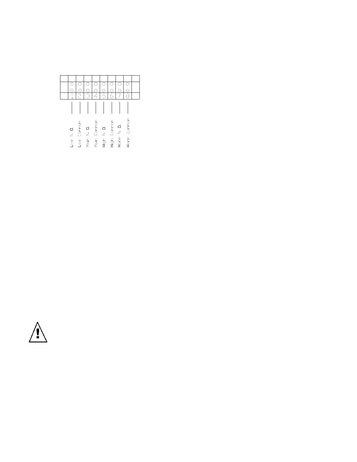
TB2 to provide a switch closure for external
control of alarms. Refer to figure 8 for a
diagram of the terminal board.
Figure 8.
Alarm-to-Relay Connection: The typical
Alarm connection uses the common
terminal and normally open (NO) terminal to
switch AC line voltage to the strobe alarm,
horn alarm or combination horn strobe.
Unless specified otherwise, SenTech
Corporation recommends the following
connections for alarms:
1. Strobe Alarm, or Strobe portion of
Combination Horn/Strobe connected
through LOW RELAY, terminals 1
and 2 on TB2.
2. Horn Alarm, or Horn portion of
Combination Horn/Strobe connected
through HORN RELAY, terminals 7
and 8 on TB2.
Caution: Ensure that external
relay connections do not touch
relay control terminals 13 and 14.
A short circuit from the exhaust
fan wiring to the relay control
wiring could damage the monitor,
the alarms or both.
Fan-to-Relay Connection: The IR-SNIF-
MCD monitor alarm relay can support a
load of up to 5 amps at line voltage. The
typical high-speed exhaust fan will have a
startup current in excess of the relay rated
amp capacity. A pilot relay or contactor will
normally be required to energize an
exhaust fan. Unless specified otherwise,
SenTech Corporation recommends the
following connections for exhaust fans:
1. Fan, pilot relay or contactor
connected through HIGH RELAY,
terminals 5 and 6 on TB2.
BMS-to-Relay Connection: The IR-SNIF-
MCD monitor alarm relay can provide alarm
indications to the typical building
management system (BMS) for Low, Main
and High alarm levels. This connection is
normally accomplished by switching a
control voltage through the normally open
(NO) contacts of the respective relay.
Unless specified otherwise, SenTech
Corporation recommends the following
relay connections for building management
systems:
1. BMS discrete input connected
through LOW, MAIN and/or HIGH
RELAYS, terminals 7 and 11.
Other External Connections
TB3 User Interface: Terminal board TB3
The IR-SNIF-1,2,3 is designed to provide
two standard 0-10 volt analog outputs or
two optional 4-20 mA analog outputs, and
external reset input and optional rs-485
interface for use with ACC 070 SenTech
COMM LINK PC to Refrigerant Monitor
Interface, or ACC 065 SenTech Remote
Control Panel Interface. Refer to figure 9
for a diagram of TB3 terminal board.
 Loading...