9
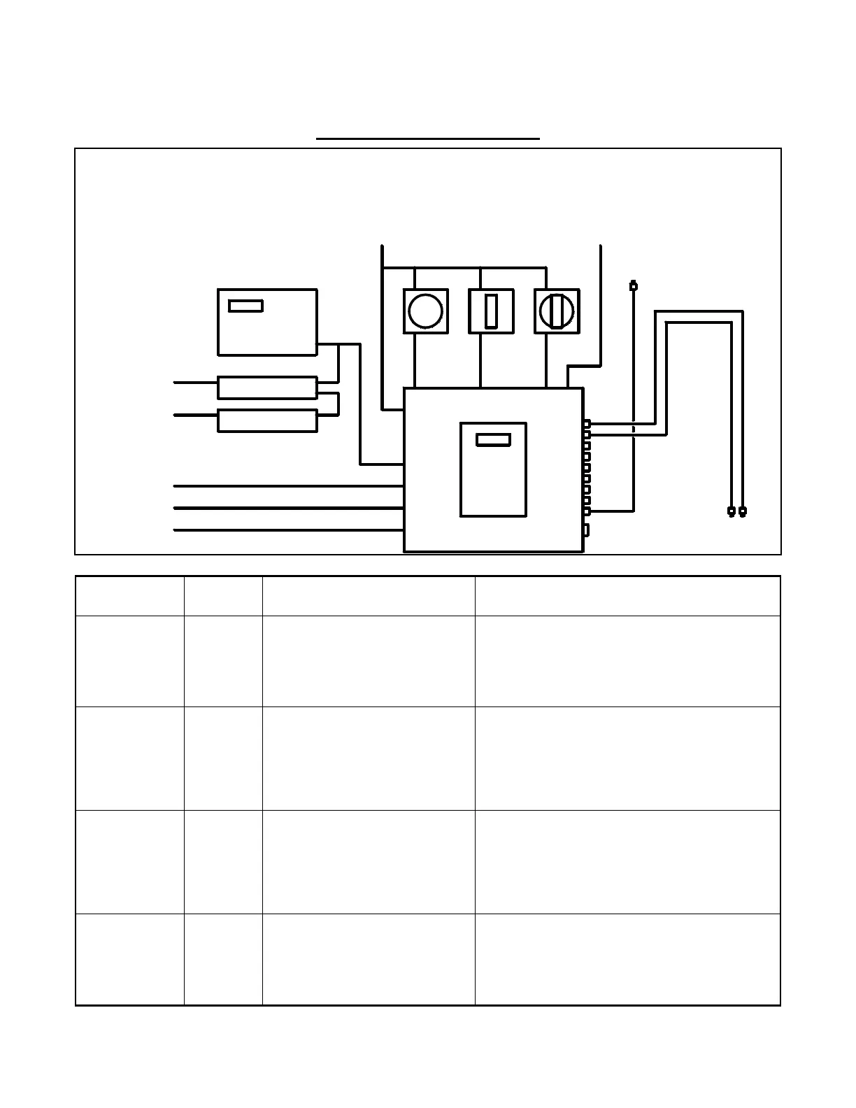
SYSTEM Block Diagram
Item Part
Number
Description Comments
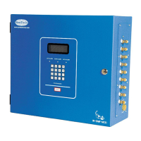
Monitor Model:
IR-SNIF-MCD1
IR-SNIF-MCD4
IR-SNIF-MCD8
IR-SNIF-MCD16
MCD1
MCD4
MCD8
MCD16
Sample Area
Connections:
ACC 030
410144
410357
1 to 16 sample tubes, routed to each
sample area
1 /4” OD 1/8” ID, FRPE Tube, 250 ft roll
Coarse Tube Filter
Barb Fitting for FRPE Tube
Terminate tube 12”-18” above floor
Purchased separately from monitor, or customer supplied
Included inside monitor
Included inside monitor
Reference Air
Connection:
ACC 030
410144
410357
Reference air for ‘Auto Zero’
1 /4” OD 1/8” ID, FRPE Tube, 250 ft roll
Coarse Tube Filter
Barb Fitting for FRPE Tube
Terminate tube in area free of refrigerants and interfering
chemicals (12”-18” from ceiling if indoors)
Purchased separately from monitor, or customer supplied
Included inside monitor
Included inside monitor
Power
Connection:
Field Wiring
120 or 240 VAC
50/60 hz
12 or 14 AWG
Voltage jumper selected inside monitor
Provided by customer, Install in accordance with NEC and
local codes
Valves
Area 1
Reference Air
Area 5
Area 6
Area 2
Area 4
Area 7
Area 8
Area 3
Exhaust
R
e
m
o
t
e
L
i
n
k
M
o
d
e
m
M
o
n
i
t
o
r
Horn
Strobe
Combo
From Circuit Breaker
To Computer
C
o
n
t
r
o
l
C
o
m
m
To Phone Line
To Fan Control
Analog To BMS
Binary To BMS
Binary To BMS
(AC power)
(switched AC)
(switched AC)
(switched AC)
(switched AC or control voltage)
(rs-485)
(dry contacts)
(optional individual alarm relays - control voltage only)
(0-10 vdc or optional 4-20mA)
(cat-3) (rs-232)
(rs-232)
(sample tube and filter)
(sample tube and filter)
(sample tube and filter)
 Loading...