6
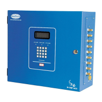
Control Electronics: Refer to the figure 4 for control electronics block diagram. The signal
from the infrared bench is analyzed by the control circuit and converted into a digital
measurement in ppm (parts per million). The ppm level is compared to trip points set for Low,
Main and High alarm levels. If the ppm level exceeds the Low alarm threshold, the “Leak Wait”
algorithm is used to determine whether the monitor has experienced a transient exposure, or a
leak truly exists. If the ppm level remains above the Low alarm threshold on completion of leak
wait, the Low alarm relay is energized. If the signal continues to increase, the Main alarm
relay will be energized and ultimately the High alarm relay. Once the system enters Low, Main
or High alarm, it will remain in that mode until the problem is cleared and the system is reset.
IR Bench
Press. Switch
Relays
Terminal Board
Control Electronics
LOW MAIN HIGH
Valves
Area 1
Reference Air
POWER SUPPLY
Valve Driver Board
TB3
Terminal Board
TB4 (opt.)
HORN
Area 5
Area 6
Area 2
Area 4
Area 7
Area 8
Area 3
Figure 4 Control Electronics Diagram
 Loading...