7 SEP LEM012SJ 2015 V01
- We recommend that the connecting wire which is used to connect the meter
to outside the circuit should be sized according to local codes and regulations
for the ampacity of the circuit breaker or over current device used in the
circuit.
- A external switch or a circuit-breaker should be installed on the inlet wire,
which will be used as a disconnection device for the meter. And it is
recommended that the switch or circuit-breaker is near the meter. The switch
or circuit-breaker should comply with the specifications of the building
electrical design and all local regulations.
- An external fuse or thermal cut-off which is used as a overcurrent protection
device for the meter must be installed on the supply side wire, and it is
recommended that the overcurrent protection device be near the meter. The
overcurrent protection device should comply with the specifications of the
building electrical design and all local regulations.
- This meter can be installed indoor directly, or in a meter box which is
waterproof outdoor, in compliance with the local codes and regulations.
- The meter has to be installed in a good ventilated and dry place.
- The meter has to be installed in a protection box in dangerous or dusty
environment.
- The meter can be installed and used after being tested in accordance with the
specifications of the building.
- The meter can be installed on a 35mm DIN rail.
- The best way to install the meter in an available height so that it is easy to
read.
- When the meter is installed in an area with frequent surges due to e.q.
thunderstorms, welding machines, inverters etc, protect the meter with
applicable Surge Protection Devices.
- After finishing installation, the meter must be sealed to prevent tampering.
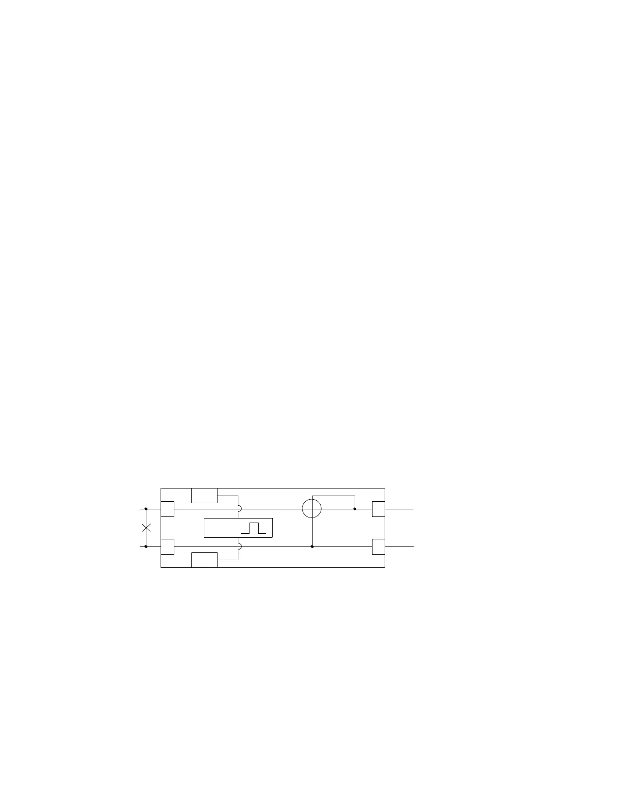
- Connection of the wires should be done in accordance with the underneath
connection diagram.
1 Inlet phase line
4 Inlet neutral line
3 Outgoing phase line
6 Outgoing neutral line
20 and 21 Pulse output contact
 Loading...