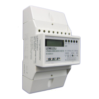
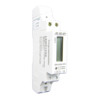
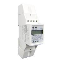
The LEM022SJ is a DIN rail three-phase four-wire active energy meter designed for direct measurement of electrical energy. It operates at 230V/400V, with a current range of 5(80A) and a frequency of 50Hz, adhering to accuracy class 1 according to IEC 62053-21.
Function Description:
The LEM022SJ energy meter is an advanced electronic kWh meter that measures active energy consumption in a three-phase four-wire system. It features a white backlight LCD display for showing energy data and indication messages. The meter is equipped with a pulse output for remote reading and accuracy testing, generating pulses proportional to the measured energy. It also includes LED indicators for power supply, consumption, and reverse current flow.
Important Technical Specifications:
- Reference Voltage (Un): 230/400V AC (3~)
- Operational Voltage: 161/279 – 300/520V AC (3~)
- Current Range: Minimum current (Imin) 0.25 A, Transitional current (Itr) 0.5 A, Reference current (Iref) 5 A, Maximum current (Imax) 80 A. The operational current range is 0.25A - 80A.
- Over Current Withstand: 3000A for 0.01s
- Operational Frequency Range: 50Hz ±10%
- Accuracy Class: Class 1 (IEC 62053-21)
- Insulation Capabilities: AC voltage withstand 2KV for 1 minute, Impulse voltage withstand 6KV – 1.2µS waveform.
- Internal Power Consumption: ≤2W / 10VA per phase
- Test Output Flash Rate (PULSE LED): 400 pulses per kWh (2.5Wh/imp)
- Pulse Output Rate (pins 26 & 27): 400 pulses per kWh (2.5Wh/imp)
- Pulse Supply Current: Ui max=27V / Ii max 27mA
- Operating Humidity: ≤ 75%
- Storage Humidity: ≤ 95%
- Specified Operating Temperature: -10°C - +40°C (3K5)
- Limit Operating Temperature: -25°C - +55°C (3K6)
- Storage Temperature: -40°C - +70°C (1K5)
- Protection Against Penetration of Dust and Water: IP51
- Insulating Encased Meter of Protective Class: II
- Data Display Mode: 7+1 digits for LCD display
- Data Save: Data can be stored for more than 20 years when power is cut.
- Dimensions: Height 140 mm, Width 70 mm, Depth 64 mm
- Weight: 0.53 Kg (net)
- Material:
- Front plate: Transparent inflaming retarding polycarbonate
- Cover, Base, Protection cover: Fiber-glass reinforced inflaming retarding polycarbonate
Intrinsic Errors (with balanced loads):
- Imin ≤ I < Itr: Cosp = 1 (±1.5%), Cosp = 0.5L (±1.0%), Cosp = 0.8C (±1.0%)
- Itr ≤ I ≤ Imax: Cosp = 1 (±1.0%)
Intrinsic Errors (with single phase load):
- Itr ≤ I ≤ Imax: Cosp = 1 (±2.0%), Cosp = 0.5L (±2.0%)
Usage Features:
- LCD Display: The meter is equipped with a white backlight LCD display that is always on during normal working hours. It shows 7+1 digits of total energy data in kWh, which cannot be reset by the user.
- Working Indication: Three power indicating LEDs (yellow for L1, green for L2, red for L3) on the front panel indicate the normal operation of each phase. If a phase fails or has no power, its corresponding LED will turn off.
- Consumption Indication: A PULSE LED on the front panel flashes to indicate power consumption. The faster the flash rate, the higher the consumption. The flash rate is 400 impulses per kWh (2.5Wh/imp).
- Reverse Indication: A REV. LED on the front plate lights up when the load current flow is reversed. The LCD display will show "HELP 1" every 3 seconds in this condition.
- Meter Version Display: Upon power-on, the meter displays its version for 3 seconds.
- Pulse Output: The meter provides a fully separated, polarity-dependent, passive transistor pulse output. This output requires an external voltage source (5-27V DC, max 27mA DC) and is connected to terminals 26 (anode) and 27 (cathode). It generates 400 pulses per kWh for remote reading and testing.
- Installation: The meter is designed for installation on a 35mm DIN rail. It can be installed indoors directly or in a waterproof outdoor meter box, in a well-ventilated and dry place, or in a protection box in dusty/dangerous environments. It is recommended to install the meter at an accessible height for easy reading.
- Surge Protection: If installed in areas with frequent surges (e.g., due to thunderstorms, welding machines, inverters), the meter should be protected with applicable Surge Protection Devices.
- Connection Diagram: The manual provides a detailed connection diagram for L1, L2, L3 phase wires, neutral wire, and pulse output contacts (26 and 27).
Maintenance Features:
- Safety Instructions: The manual emphasizes strict adherence to safety instructions, including using isolated tools, not connecting while the circuit is live, placing the meter in dry surroundings, and not mounting it in explosive areas or exposed to dust, mildew, and insects.
- Qualified Personnel: Commissioning, operation, installation, maintenance, and repair must only be performed by qualified personnel authorized to work with electrical devices.
- Seals and Warranty: Users are explicitly warned not to break the seals or open the front cover, as this will void the warranty. The warranty period is 12 months after purchase and covers only construction faults.
- Physical Impact: Avoid dropping or subjecting the meter to physical impact, as it contains high-precision components that can be damaged.
- Wiring: Ensure that the used wires are suitable for the meter's maximum current. AC wires must be connected correctly before activating current/voltage. Do not touch connecting clamps with bare hands, metal, or blank wire.
- Protection Cover: The protection cover must be placed after installation to prevent electric shock.
- Overcurrent Protection: An external fuse or thermal cut-off, or a single-pole circuit breaker, should be installed on the supply side as an overcurrent protection device, near the meter for operator convenience. It should comply with local codes and regulations.
- Troubleshooting Guide: The manual includes a troubleshooting section to address common issues such as no light for power supply/consumption indicators, the register not running, LCD backlight not lit, no pulse output, or incorrect pulse output rate. Solutions typically involve checking power supply connections, verifying correct wiring, ensuring sufficient operating power, or contacting a qualified technician for replacement if an internal circuit fault is suspected.
- Data Retention: The meter is designed to store energy data for more than 20 years even during power cuts.