7 LEM022SJ 2015 V01
recommended that the overcurrent protection device is near the meter so that
it is convenience for the operator. The overcurrent protection device should
comply with the specifications of the building electrical design and all local
regulations.
- This meter can be installed indoor directly, or in a meter box which is
waterproof outdoor, in compliance with local codes and regulations.
- The meter has to be installed in a good ventilated and dry place.
- The meter has to be installed in a protection box in dangerous or dusty
environment.
- The meter can be installed and used after being tested in concordance with
the specifications.
- The meter can be installed on a 35mm DIN rail.
- The best way to install the meter is in an available height so that it is easy to
read.
- When the meter is installed in an area with frequent surges due to e.q.
thunderstorms, welding machines, inverters etc., protect the meter with
applicable Surge Protection Devices.
- After finishing installation, the meter must be sealed to prevent tampering.
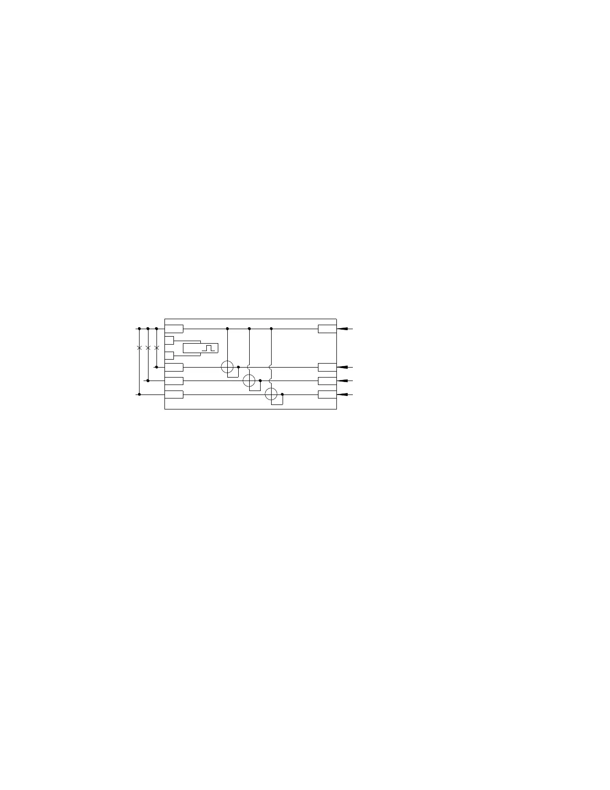
- Connection of the wires should be done in accordance with the underneath
connection diagram.
L1 L1 phase wire
L2 L2 phase wire
L3 L3 phase wire
N Neutral wire
26 and 27 Pulse output contact
1.9 Operating
Working indication
On the LEM022SJ front panel, there are three power indicating LED which have
different color from each other. The yellow LED represent L1 phase; the green LED
represent L2 phase; the red LED represent L3 phase. When any phases work normally,
the LED representation will be on. When any phases have failure or no power, the LED
will turn off.
Consumption indication
There is a PULSE LED which is used as indicating power consumption in the front panel
of LEM022SJ. When consumption happens, the LED will flash. The more quickly LED
flash, the more consumption there is. For this LED, the flash rate is 400 impulses per
kWh (2.5Wh/imp).