6 LEM022SJ 2015 V01
U i m a x = 2 7 V / l i ma x = 2 7m A
Th ree phase 100A kWh meter
L1
+
-
N
L2
L3
L1
L2
L3
N
SO
N O .
3
2 6
2 7
RL=2.5Wh/imp RA=2.5Wh/imp
R
A
=
2
. 5
W
h
/ im
p
(t i =
8
0
m
s
) S
O
R
L
=
2
. 5
W
h
/ i m
p
L 1 L 2 L 3PUL S ER E V.
3 PHASE 4 WIRE ENERGY METER
EN50470-3
EN50470-3
B
230/400V, 0 .25-5(100) A, 50 Hz
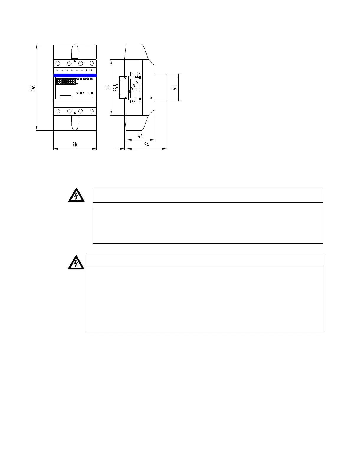
1.8 Installation
- We recommend that the connecting wire which is used to connect the meter
to the outside circuit should be sized according to local codes and regulations
for the ampacity of the circuit breaker or over current device used in the
circuit.
- An external switch or a circuit-breaker should be installed on the inlet wire,
which will be used as a disconnection device for the meter. And it is
recommended that the switch or circuit-breaker is near the meter.
convenience for the operator. The location of the switch or circuit-breaker
should comply with the specifications of the building electrical design and all
local regulations.
- An external fuse or thermal cut-off which is used as a overcurrent protection
device for the meter must be installed on the supply side, and it is
Turn off and lock out all power supplying the energy meter and the
equipment to which it is installed before working on it.
Always use a properly rated voltage sensing device to confirm that
power is off.
Installation should be performed by qualified personnel familiar with
applicable codes and regulations.
Use isolated tools to install the meter.
Fuse or thermal cut-off or single-pole circuit breaker can’t be fitted on
the supply line and not the neutral line.
Case is sealed, failure to observe this instruction can result in damage for
meter.
No warranty if case is opened or removed seal or damage.