AsteRx-m3 OEM
7
2.1 Mounting
The four mounting holes are compatible with M3 screws. Use M3 3.5mm spacers. An
example of applicable SMD spacer is THF-1.6-3.5-M3 from MAC8.
All mounting holes are grounded, and should preferably be connected to ground on the
host PCB. Note however that the mounting holes should not be relied on as only ground
return connection: a proper ground should be supplied to the GND pins of the I/O
connector(s) as well.
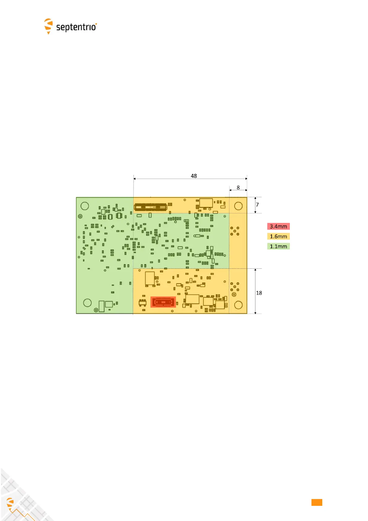
The maximum height of the components at the bottom side of the AsteRx-m3 OEM board
is within the mask shown below. The maximum component height is 1.1mm in the green
area and 1.6mm in the yellow area.
2.2 Environmental
Operational: -40 to +85 °C
Storage: -55 to +85 °C
2.3 Power and Power Consumption
The board is powered through pin#1 and pin#2 of the 30-pin connector. Power supply
voltage must be 3.3V +/-5%.
The power consumption depends on the set of GNSS signals enabled with the
setSignalTracking command.
 Loading...