AsteRx-m3 OEM
8
The following table shows the typical power consumption for selected sets of signals. The
dual antenna configuration corresponds to a receiver where the option to track from the
AUX1 antenna is enabled.
Enabling the built-in L-Band demodulator with the setLBandSelectMode command adds
100 mW.
Enabling wideband interference mitigation with the setWBIMitigation command adds
160 mW (dual antenna) or 80mW (single antenna).
Consumption in standby mode: 3 mW
Note that the power consumption in the above table are average values. To account for
peak currents, the minimum power supply drive capability should be 1 Ampere.
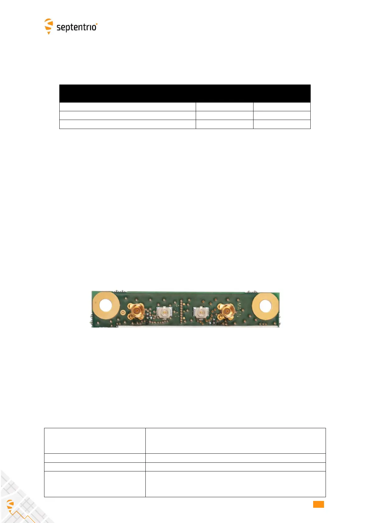
2.4 RF Interface
For illustration purposes, the above picture shows both u.FL and MMCX connectors. In
reality, only one type of connector is available depending on the board variant.
The main antenna must be connected to the u.FL or MMCX connector marked “MAIN” on
the PCB and the auxiliary antenna must be connected to the AUX1 connector.
2.4.1 Electrical Specifications
3-5.5V DC, set via pin#18 of the 30-pin connector. The same
voltage is applied to both antennas. If pin#18 is not
connected, there is no DC voltage to the antennas.
15-50 dB
For optimal performances, the net gain on MAIN and AUX1
must not differ by more than 10dB.
 Loading...