CONTENTS
1. APPLICATIONS & FEATURES......................... 1 6.1 Preparation....................................................... 8
2. SPECIFICATIONS............................................... 1 6.1.1 Control Buttons................................................ 8
3. FRONTAL & BACK OPERATION PANELS..... 2 6.1.2 Power Lead Connection................................... 9
4. STRUCTURE INSTRUCTION............................ 3 6.1.3 Control Line Connection................................. 9
4.1 ±15V Power Supply............................................ 3 6.2 Operation Method............................................ 9
4.2 +5.00V Nominal Power Supply............................ 3 6.2.1 Turn On............................................................ 9
4.3 Displayer.............................................................. 3 6.2.2 Zero Adjustment.............................................. 9
4.4 Valve Controller................................................... 4 6.2.3 Valve Controller Setting.................................. 9
4.5 Zero Potentiometer............................................... 4 6.2.4 Setting.............................................................. 9
4.6 Setting Potentiometer........................................... 4 6.2.5 Turn Off.......................................................... 9
4.7 Power Supply Switch........................................... 4 7. Parameter Setting............................................. 9
4.8 Power Supply Connector...................................... 4 7.1 Range Selection............................................... 10
4.9 Fuse ..................................................................... 4 7.2 Range Adjustment ........................................... 10
4.10 Setting Selection................................................... 4 7.3 Radix Point Adjustment................................... 10
4.11 MFC “D” Connector ........................................... 5 8. MAINTENANCE............................................ 10
4.12 External Control Connector.................................. 5 8.1 Internal Potentiometer Adjustment.................. 10
4.13 Nameplate............................................................ 5 8.2 Grounding Problem......................................... 10
5. INSTALLATION & CONNECTION................... 5 8.3 Substitution..................................................... 11
5.1 Dimension............................................................ 5 9. PRODUCTION SELECTION.......................... 11
5.2 MFC Connection.................................................. 6 9.1 Type Selection ................................................ 11
5.3 External Control Connection................................ 7 9.2 Order form....................................................... 12
6. OPERATION PROCEDURE............................... 8
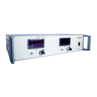
D08 SERIES FLOW READOUT BOXES