Do you have a question about the SEW-Eurodrive Movidrive MD_60A Series and is the answer not in the manual?
| Brand | SEW-Eurodrive |
|---|---|
| Model | Movidrive MD_60A Series |
| Category | DC Drives |
| Language | English |
Safety and warning instructions for the unit.
Intended applications and operating conditions for MOVIDRIVE® drive inverters.
Forbidden uses and conditions for the unit's application.
Requirements for safety functions and higher-level precaution systems.
Guidelines for environmentally sound disposal of electronic waste materials.
Safety instructions and regulations for installation and startup procedures.
Safety precautions for operating and servicing the unit, including high voltages.
Details on unit identification, nameplates, and the scope of delivery.
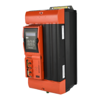
Description and component identification for MOVIDRIVE® size 1 unit.
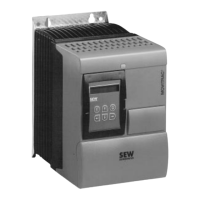
Description and component identification for MOVIDRIVE® size 2 unit.
Description and component identification for MOVIDRIVE® size 3 unit.
Description and component identification for MOVIDRIVE® size 4 unit.
Description and component identification for MOVIDRIVE® size 5 unit.
Instructions for basic unit installation, including torques and clearances.
Requirements for UL compliant installation, including cable and fuse specifications.
Instructions for installing power shield clamps for sizes 1 and 2 units.
Installation of touch guards for sizes 4 and 5 units to achieve IP10 enclosure.
Wiring diagram for the power section and brake connections.
Table assigning braking resistors, chokes, and filters for 400/500 V units, sizes 1 & 2.
How to connect the system bus (SBus), including wiring, cable specs, and terminating resistor.
How to connect the RS-485 interface, including wiring, cable specs, and terminating resistor.
Details on connecting the USS21A option for RS-232 and RS-485 interfaces.
Table showing possible combinations of optional interface boards for MDF/MDV/MDS units.
Procedures for safely installing and removing option PCBs.
Connection and terminal details for the DIO11A option, including voltage input.
General notes, shield contact, and pre-fabricated cables for encoder/resolver connections.
How to set up incremental encoder simulation output.
Connecting two MOVIDRIVE® units for master/slave operation.
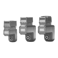
General instructions for drive startup, including requirements and motor combinations.
Preparations and resources needed before starting up the inverter.
Using the DBG11A keypad for startup, required data, and encoder types.
Startup of the speed controller and its menu structure.
General information and steps for starting up using PC and MOVITOOLS software.
How to start the motor using analog setpoints and associated wiring.
List of parameters available in the short menu.
Parameters related to setpoints and ramp generation.
Parameters for speed control, hold control, synchronous operation, and synchronization.
Parameters for motor characteristics and speed/current reference signals.
Parameters for monitoring functions and terminal assignments.
Parameters for analog outputs and operating modes.
Explanation of operating status displayed on the 7-segment display and DBG11A keypad.
Details on fault memory, switch-off responses, reset procedures, and timeout active status.
Fault codes, messages, reactions, causes, and measures.
How to contact SEW electronics service and information required for repair.
General technical specifications for MOVIDRIVE® MD_60A inverters.
Technical data for Size 1 units (400/500 V), including motor combinations.
Technical data for Size 2 units (400/500 V), including motor combinations.
Technical data for Size 3 units (400/500 V), including motor combinations.
Technical data for Size 4 units (400/500 V), including motor combinations.
Technical data for Size 5 units (400/500 V), including motor combinations.
Technical data for Size 1 units (230 V), including motor combinations.
Technical data for Size 2 units (230 V), including motor combinations.
Technical data for Size 3 units (230 V), including motor combinations.
Technical data for Size 4 units (230 V), including motor combinations.
General electronics data for the MOVIDRIVE® MD_60A units.
Key to abbreviations used throughout the manual.
Alphabetical index of topics covered in the manual.