Do you have a question about the SEW-Eurodrive Movigear Performance MGFAS2-DFC-C and is the answer not in the manual?
| Brand | SEW-Eurodrive |
|---|---|
| Model | Movigear Performance MGFAS2-DFC-C |
| Category | DC Drives |
| Language | English |
General safety notes for preventing injury and damage.
User responsibilities regarding safety compliance and qualified personnel.
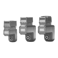
Describes the composition of MOVIGEAR® performance drive units.
Details the available shaft variants: hollow shaft with keyway and TorqLOC®.
Explains torque arm mounting and housing with threads.
Provides an example nameplate and explains the type designation structure.
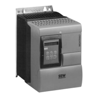
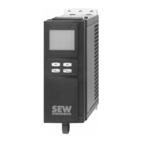
Details the electronics cover and connection box components.
Shows nameplate examples and type designation for electronics.
Provides nameplate and type designation examples for connection units.
Important safety warnings and notes for installation and disassembly.
Notes on mounting, cleaning, alignment, cooling, and cable glands.
Installation steps for TorqLOC® units with specific shaft types.
Installation steps for TorqLOC® units with contact shoulders.
Notes on arranging, routing, and EMC-compliant installation components.
Shows terminal assignments for line, braking resistor, control, and fieldbus interfaces.
Illustrates the connection diagram for MOVIGEAR® performance units.
Explains connecting a PC via interface adapters or Ethernet.
Essential safety notes and information before startup.
Lists required hardware and software components for startup.
Overview and functions of DIP switches S1, S2, and S3.
Outlines segments of the startup procedure using MOVISUITE®.
Using MOVISUITE® for manual operation and activating/deactivating manual mode.
Functional description and torques of the electrodynamic deceleration function.
Steps to activate or deactivate the DynaStop® function.
Describes DynaStop® operation with the STO function.
Troubleshooting options for mechanical drive malfunctions.
Guides on evaluating fault messages using MOVISUITE®.
Details faults with configurable responses and index numbers.
Instructions for acknowledging and resetting fault messages.
Explains the meaning of LEDs for PROFINET, EtherNet/IP™, Modbus TCP, and POWERLINK.
Lists standard faults, their causes, and measures for correction.
Details faults according to the CiA402 profile, including causes and measures.
Provides instructions for replacing electronic covers, memory modules, and drive units.
Information on contacting SEW-EURODRIVE service for repairs and sending units.
Table detailing inspection and replacement intervals for drive units.
Preliminary work, changing oil, painting, cleaning, and replacing components.
Data required for defining drive components and determining motor data.
Project planning procedure and flow diagram for MOVIGEAR® performance.
Checks for DynaStop® usability and application velocity calculations.
General technical data for MOVIGEAR® performance types.
Operating range and torque data for DynaStop®.
Schematic characteristic curves and exact values for torque.
Installation and disassembly using SEW-EURODRIVE kits.
Dimension sheets for various MOVIGEAR® performance models.
MOVIGEAR® performance safety technology and safe condition definition.
Requirements for installation, startup, and operation of drive safety functions.
General information and requirements for using safety relays and controllers.
Tested safety class, failure probability, service life, and safe state.