Do you have a question about the SEW-Eurodrive Movigear Performance MGF**-DFC-C Series and is the answer not in the manual?
| Brand | SEW-Eurodrive |
|---|---|
| Model | Movigear Performance MGF**-DFC-C Series |
| Category | DC Drives |
| Language | English |
States that the product must not perform safety functions without a higher-level system.
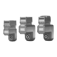
Describes the MOVIGEAR® performance drive units composed of gear unit, motor, and drive electronics.
Details the electronics cover (inside) and connection box components.
Provides notes on mounting, changing positions, and handling the electronics cover.
Describes installation notes, tolerances, and disassembly for shaft-mounted units with keyway.
Details the installation procedure for units with TorqLOC® and customer shafts without contact shoulders.
Details the installation procedure for units with TorqLOC® and customer shafts with contact shoulders.
Covers notes on arranging components, EMC-compliant installation, and cable selection.
Provides detailed terminal assignments for line terminals, braking resistor, control terminals, and fieldbus interfaces.
Shows the connection diagram for MOVIGEAR® performance MGF..-DFC-C.
Details representation of connections, designation keys, and connection cables.
Explains how to connect a PC to the drive unit via interface adapter or Ethernet.
Provides an overview and detailed functions of the drive unit's DIP switches.
Illustrates the startup procedure segments using MOVISUITE® software.
Explains how to use the manual mode function of the MOVISUITE® engineering software.
Provides functional description and torques for the DynaStop® electrodynamic retarding function.
Shows how to evaluate fault messages using MOVISUITE®.
Details fault messages with parameterizable responses and their index numbers.
Explains the LEDs for PROFINET IO, EtherNet/IP™, Modbus TCP, and POWERLINK designs.
Lists standard faults, their causes, responses, and measures.
Lists faults according to the CiA402 profile, including causes and measures.
Provides warnings and procedures for replacing electronic covers, memory modules, and drive units.
Information on contacting SEW-EURODRIVE Service and sending units for repair.
Details inspection and replacement intervals for drive units based on operating hours and time.
Preliminary work and specific tasks for inspection and maintenance.
Lists specifications required for precise drive component definition.
Illustrates the project planning procedure for MOVIGEAR® performance.
Provides functional description and checks for DynaStop® usage.
Lists general technical data for MOVIGEAR® performance types.
Overview of integrated and external braking resistors.
Details the safety technology developed and tested according to safety requirements.
Explains STO (Safe Torque Off) and SS1(c) functions.
Mandatory requirements for installing and operating in safety-related applications.