3
Unit structure
Electronics
Operating Instructions – MOVIGEAR
®
performance
25
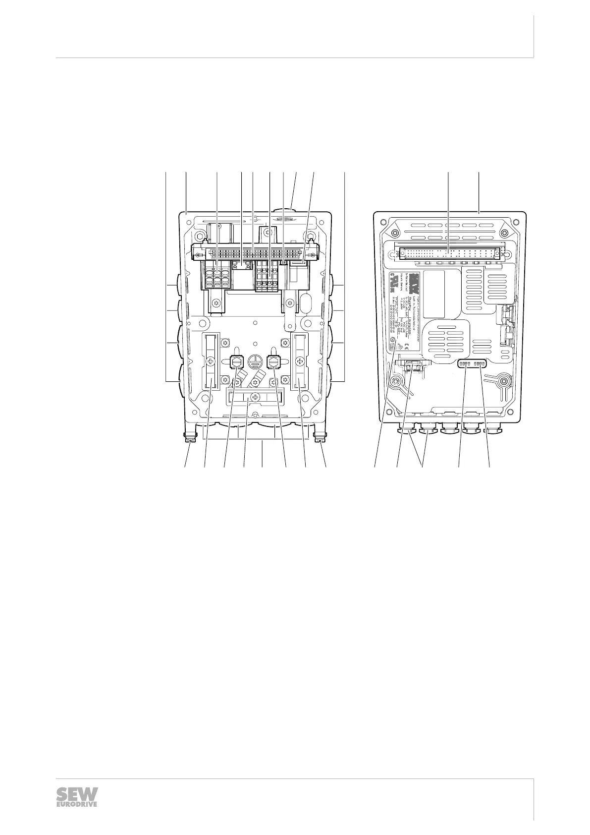
3.10 Electronics
3.10.1 Electronics cover (inside) and connection box
The following figure shows the connection box and the bottom side of the electronics
cover:
S1 1 2 3 4 1 2 3 4 S2
OnOn
[2] [7][3] [5] [5][4] [6] [1][1] [1] [9]
[14]
[14][1] [14] [13] [10][14]
[8]
[11][12] [7][15] [15] [15]
9007224383194123
[1] Cable glands
[2] Connection box
[3] Line connection L1, L2, L3
[4] Braking resistor connection
[5] Plug connector connection unit for electronics cover
[6] Electronics terminal strip
[7] Fieldbus connection (depends on the configured connections)
[8] Engineering interface
[9] Electronics cover
[10] DIP switches S1/1–S1/4
[11] DIP switches S2/1– S2/4
[12] Replaceable memory module
[13] Electronics cover nameplate
[14] Screws for PE connection
[15] Shield clamp
25945475/EN – 04/2019

 Loading...