Do you have a question about the SEW-Eurodrive MOVITRAC MCX91A-0017-2.3-4 Series and is the answer not in the manual?
| Type | Inverter |
|---|---|
| Model | MCX91A-0017-2.3-4 |
| Series | MOVITRAC |
| Power Rating | 2.3 kW |
| Rated Power | 2.3 kW |
| Frequency Range | 0 - 400 Hz |
| Control Method | V/f Control, Vector Control |
| Protection Class | IP20 |
| Communication Interface | CANopen, EtherCAT, Modbus |
| Ambient Temperature | -10 to +40 °C |
| Relative Humidity | 5 to 95%, non-condensing |
| Altitude | Up to 1000 m |
Explains the graduation and meaning of signal words and hazard symbols.
Defines the qualifications required for specialists and instructed persons.
Specifies the intended applications and limitations of the product.
Describes the STO safety subfunction and other safety options.
Provides instructions for safely handling and transporting the device.
Guidelines for ensuring a safe work environment before product interaction.
Detailed safety procedures for electrical work on the device.
Safety precautions related to installation and assembly procedures.
Details requirements for protective separation of power and electronics.
Ensures correct attachment of covers and compliance with regulations.
Safety notes for initial startup and ongoing operation of the device.
Details the information provided on system and performance data nameplates.
Explanation of the product's type designation codes and their meanings.
Defines various certification marks and their compliance.
General guidelines for installing the inverter in a control cabinet.
Checks for device integrity, ambient temperature, and conditions.
Provides drilling diagrams and dimensions for control cabinet preparation.
Step-by-step guide for mounting inverter sizes 0S and 0L.
Step-by-step guide for mounting inverter sizes 3 through 8.
Instructions for installing shield plates for cable shielding.
Step-by-step instructions for removing and attaching the safety cover.
Procedure for removing and reinstalling touch guards on inverters size 5+.
Guidelines for installing braking resistors due to high temperatures.
Instructions for installing the line choke near the inverter.
Recommendations for optimizing system EMC and eliminating interference.
Guidelines for routing power, control, and signal cables separately.
General measures to prevent unintentional motor start-up and ensure safety.
Table of permitted tightening torques for various terminal connections.
Table of permitted cable cross sections for rigid and flexible conductors.
Guidelines for selecting appropriate residual current devices.
Overview of when a line contactor is required and its proper use.
Details cable cross sections for PE connection based on leakage current.
Information regarding UL requirements and label attachment.
Torque and wire size specifications for field wiring power terminals.
Requirements for branch circuit protection according to electrical codes.
Details the internal and external 24 V supply voltage capabilities.
Properties for fuses and miniature circuit breakers used for protection.
Instructions for connecting ohmic loads like braking resistors.
Safety warning and connection details for temperature sensors.
Notes on connecting brake cables, including shielding recommendations.
Notes on digital inputs/outputs, shielding, and cable length.
Installation notes for encoders, including EMC screw fittings.
Instructions for disconnecting the MOVILINK® DDI connector.
Procedure for routing fieldbus cables and connecting them.
Protection against thermal overload for braking resistors.
Notes on connecting the line choke and line filter.
Details terminal assignments for basic device, size 0S 3-phase and 1-phase.
Shows power connection wiring for size 0S 3-phase with components.
Details the assignment of signal terminals and connections for electronics.
Wiring for control electronics at the top and bottom of the unit.
Key and general diagrams for brake control connections.
Steps to perform before initial startup, including safety warnings.
Specific safety warnings and procedures for lifting applications.
Prerequisites for startup: mechanical, electrical, and safety measures.
Lists necessary hardware for startup using MOVISUITE® software.
Details on pre-assigned terminal functions for initial motor operation.
Information on products with pre-configured customer parameters.
Procedure for starting up third-party asynchronous and synchronous motors.
Guidance on using MOVISUITE® for motor startup and parameter measurement.
Procedure for setting the EtherCAT® ID using hexadecimal switches.
Motors that can be started up using the CBG21A keypad.
Automatic startup of motors with MOVILINK® DDI interface.
Overview of control options: digital inputs, analog inputs, fieldbus.
Default settings for digital inputs, outputs, and analog inputs.
Setting the source to 'Standard fieldbus system' for fieldbus control.
Using MOVIKIT® software modules with MOVISUITE®.
Starting up applications with specific settings using MOVISUITE®.
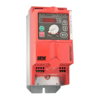
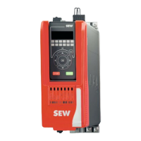
Description of the CBG22A keypad, its display, and keys.
Procedure for acknowledging and resetting fault messages.
Explains the 7-segment display and its operating states.
Details various device states indicated by the 7-segment display.
Codes for normal operation states shown on the 7-segment display.
Explains fault codes displayed as flashing numerical values.
Overview of LED positions and their labels for different variants.
General meaning and measures for the 'DRIVE' LED.
Status indications and causes for the PROFINET 'BF' LED.
Meaning and measures for the 'NS' LED in Ethernet/Modbus variants.
Meaning of 'BS' and 'BE' LEDs for POWERLINK CFL variant.
Procedures for replacing a device with identical or different units.
Safety warnings and procedures for shutting down the device.
Instructions for disposing of the product and its components according to regulations.
Recommended checks for connection cables and cooling fins.