Do you have a question about the SEW-Eurodrive Movidrive MDX61B and is the answer not in the manual?
| Brand | SEW-Eurodrive |
|---|---|
| Model | Movidrive MDX61B |
| Category | Inverter |
| Language | English |
Provides information about the current version and intended audience of the documentation.
Explains the grading and meaning of signal words and hazard symbols used in safety notes.
Information essential for fault-free operation and fulfillment of limited warranty claims.
States SEW-EURODRIVE's liability limitations regarding non-observance of instructions.
Lists product names and trademarks used in the documentation.
Basic safety notes to prevent injury and damage during operation.
Defines authorized personnel for installation, startup, and service.
Specifies the intended use of drive inverters and applicable directives.
Provides safety notes regarding electrical installation and connection procedures.
Safety considerations for systems incorporating drive inverters.
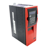
Details the type designation system, nameplate information, and scope of delivery.
Lists the components included in the scope of delivery for various device sizes.
Provides dimension drawings and terminal assignments for MOVIDRIVE® MDX60/61B size 0.
Provides dimension drawings and terminal assignments for MOVIDRIVE® MDX60/61B size 1.
Provides dimension drawings and terminal assignments for MOVIDRIVE® MDX61B size 2S.
Provides dimension drawings and terminal assignments for MOVIDRIVE® MDX60B/61B size 2.
Provides dimension drawings and terminal assignments for MOVIDRIVE® MDX61B size 3.
Provides dimension drawings and terminal assignments for MOVIDRIVE® MDX61B size 4.
Provides dimension drawings and terminal assignments for MOVIDRIVE® MDX61B size 5.
Provides dimension drawings and terminal assignments for MOVIDRIVE® MDX61B size 6.
Provides dimension drawings and terminal assignments for MOVIDRIVE® MDX61B size 7.
Details the dimension drawings and terminal assignments for the MDX62B motor inverter size 7.
Covers general installation, clearances, component mounting, and wiring requirements.
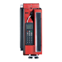
Step-by-step instructions for removing and installing the DBG60B keypad.
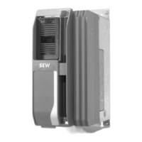
Provides procedures for removing and installing the device's front cover.
Details UL requirements, including field wiring and short circuit current ratings.
Instructions for installing shield clamps for power and signal cables on various sizes.
Explains how to install touch guards to achieve IP20 protection for power terminals.
Provides detailed wiring diagrams for power sections, brakes, and DC power supply units.
Lists the correct assignments of braking resistors, chokes, and filters for different device models.
Details the wiring and cable specifications for connecting the system bus (SBus).
Provides wiring diagrams and cable specifications for RS485 interface connections.
Describes the DWE11B/12B interface adapters for connecting HTL encoders.
Explains the connection of the UWS21B adapter for RS232 to RS485 signal conversion.
Details the connection of the USB11A adapter for PC communication.
Shows possible combinations of option cards for MOVIDRIVE® MDX61B.
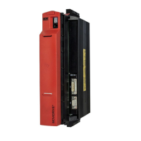
Provides instructions for safely installing and removing option cards.
Offers general installation notes and shield contact information for encoders and resolvers.
Details the connections and terminals for the DEH11B HIPERFACE® encoder card.
Describes the connections and terminals for the DEH21B absolute encoder card.
Details the connections and terminals for the DEU21B multi-encoder card.
Explains connections and terminals for the DER11B resolver option.
Lists external encoders that can be connected to X:14 on DEH11B, DEU21B, and DER11B options.
Provides wiring diagrams for connecting various encoder types to DEH11B and DER11B options.
Describes how to use X14 for incremental encoder simulation.
Explains setting up master/slave connections using X14 for internal synchronous operation.
Details the connections and terminals for the DIO11B input/output board option.
Describes the connections and terminals for the DFC11B CAN/CANopen fieldbus interface.
Provides general guidelines and prerequisites for successful inverter startup.
Details preparatory steps and necessary resources before performing startup.
Instructions for performing startup using the DBG60B keypad.
Describes how to establish communication and execute device functions using MOVITOOLS®.
Explains how to start the motor using analog setpoints, fixed setpoints, and manual operation.
Lists all available parameters, their names, and factory settings.
Describes the information shown on the 7-segment display and DBG60B keypad.
Lists and explains information messages displayed on the DBG60B or MOVITOOLS®.
Details the functions and key assignments of the DBG60B keypad.
Provides notes on installing and replacing the memory card.
Information regarding authorized repairs and component replacement.
Details fault memory, switch-off responses, and reset procedures.
Provides lists of fault codes, subfaults, possible causes, and measures.
Information on sending devices for repair and required details.
Procedure for handling devices during extended storage to prevent capacitor aging.
Details CE, UL, cUL, EAC, and RCM approvals for the device series.
Lists general technical specifications applicable to all MOVIDRIVE® MDX60/61B inverters.
Provides detailed technical data for AC 400/500 V units across various sizes.
Provides detailed technical data for AC 230 V units across various sizes.
Shows mechanical dimension drawings for MOVIDRIVE® MDX60B sizes 0S and 0M.
Displays mechanical dimension drawings for MOVIDRIVE® MDX61B sizes 0S, 0M, 1, 2S, 2, 3, 4, 5, 6, 7.
Details the description and properties of the IPOSplus® positioning and sequence control.
Describes the MDR60A/61B unit's function and UL approval.
Provides technical data for MDR60A/61B units and MDX62B motor inverter.
Shows dimension drawings and minimum clearances for MDR60A0150 size 2.
Provides dimension drawings and minimum clearances for MDR60A0370 size 3.
Shows dimension drawings and minimum clearances for MDR60A0750 size 4.
Provides dimension drawings and minimum clearances for MDR60A1320 size 6.
Shows dimension drawings and minimum clearances for MDX62B size 7.
Details cable sets for DC link connection between inverters and regenerative power supply units.
Provides part number, description, and electronics data for the HIPERFACE® encoder card.
Details part number, description, and electronics data for the resolver card.
Provides part number, description, and electronics data for the DEU21B multi-encoder card.
Details part numbers, description, and electronics data for absolute encoder cards.
Lists available adapters for quick replacement of MOVIDRIVE® A with MOVIDRIVE® B.
Describes DWE11B/12B interface adapters for connecting HTL encoders.
Provides technical data for the UWS11A interface adapter (RS232 to RS485 conversion).
Details technical data for the UWS21B interface adapter.
Provides technical data for the USB11A interface adapter for PC connection.
Details the DWI11A option for DC 5 V incremental encoder supply.
Describes the DIO11B option for expanding digital and analog I/O.
Provides technical data for the PROFIBUS DP fieldbus interface.
Details technical data for the INTERBUS fieldbus interface.
Provides technical data for the INTERBUS FOC fieldbus interface.
Details technical data for the PROFINET IO RT fieldbus interface.
Provides technical data for the DFE33B fieldbus interface.
Details technical data for the EtherCAT® fieldbus interface.
Provides technical data for the DeviceNet™ fieldbus interface.
Details technical data for the CAN/CANopen fieldbus interface.
Provides part number, description, and electronics data for the synchronous operation card.
Details technical data for PROFIBUS DP-V1 interface with PROFIsafe.
Provides technical data for PROFIBUS DP-V1 interface with PROFIsafe.
Details technical data for PROFINET IO interface with PROFIsafe.
Provides technical data for PROFINET IO interface with PROFIsafe.
Details part numbers, description, and electronics data for safety modules.
Provides part numbers, description, and electronics data for the MOVI-PLC® basic controller.
Details part number, description, and electronics data for the OST11B option.
Describes types of DH controllers and their electronics data.
Provides part numbers, description, and electronics data for BST brake modules.
Details the part number and description for the DMP11B mounting panel.
Provides part number and description for the DLB11B touch guard.
Details part number and description for the DLB21B touch guard for size 7.
Provides part number and description for the DLS11B mounting base.
Details part number and description for the DLH11B wall bracket for size 7.
Provides part number and description for the DLA11B connection kit.
Details part number and description for the DLK11B air duct for size 7.
Provides part numbers and description for DLZ11B DC link couplings.
Details part number and description for the 2Q DLZ12B DC link adapter.
Provides part number and description for the 4Q DLZ14B DC link adapter.
General information, UL approval, parallel connection, mounting position, and assignments.
Details the dimension drawings and technical data for ND line chokes.
Provides technical data and dimension drawings for NF line filters.
Details technical data and dimension drawings for HD output chokes.
Provides technical data and dimension drawings for HF output filters.
Contains the EU Declaration of Conformity for MOVIDRIVE® frequency inverters.
EU Declaration of Conformity for MOVIDRIVE® with DFS11B/DFS21B options.
EU Declaration of Conformity for MOVIDRIVE® with DCS2.B/DCS3.B options.
Contact information for SEW-EURODRIVE in Algeria.
Contact information for SEW-EURODRIVE in Argentina.
Contact information for SEW-EURODRIVE in Australia.
Contact information for SEW-EURODRIVE in Austria.
Contact information for SEW-EURODRIVE in Bangladesh.
Contact information for SEW-EURODRIVE in Belarus.
Contact information for SEW-EURODRIVE in Belgium.
Contact information for SEW-EURODRIVE in Brazil.
Contact information for BEVER-DRIVE in Bulgaria.