Do you have a question about the SEW-Eurodrive MOVIDRIVE Series and is the answer not in the manual?
| Brand | SEW-Eurodrive |
|---|---|
| Model | MOVIDRIVE Series |
| Category | Inverter |
| Language | English |
Safety notes marked with icons for electrical, mechanical hazards, and important instructions.
Notes on matching the inverter to the application and potential unexpected behavior.
Describes the MOVIDRIVE® inverter's DeviceNet operation and parameter exchange.
Explains hardware switches for MAC-ID and baud rate settings and automated parameter setting.
Discusses monitoring functions like fieldbus timeout and diagnostic options.
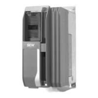
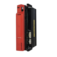
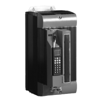
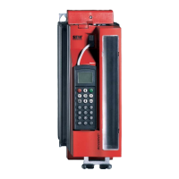
Lists the MOVIDRIVE® series drive inverters compatible with the DFD11A option.
Step-by-step guide for installing the DeviceNet option card into the drive inverter.
Details the pin assignment for the CAN bus connection terminals.
Provides measures for effective shielding and proper routing of DeviceNet bus cables.
Explains the necessity and method of bus termination with 120 Ω resistors.
Describes how to set MAC-ID and baud rate using DIP switches on the DFD11A card.
Overview of the 4 bicolor LEDs (ModNet, PIO, BIO, BUSOFF) on the option card.
Details the LED status during the power-up test sequence.
Explains the functions and status indications of the ModNet LED.
Describes the functions and status indications of the PIO LED for polled I/O.
Explains the functions and status indications of the BIO LED for bit-strobe I/O.
Details the functions and status indications of the BUSOFF LED for bus node status.
Guides setting the inverter to fieldbus control mode using parameters P100 and P101.
Step-by-step procedure for enabling the inverter and setting control modes via fieldbus.
Instructions on installing the EDS file for the DFD11A option card using DeviceNet Manager.
Explains how EDS files are read and devices appear in the DeviceNet Manager.
Details the polled I/O messages and setting process data length.
Details the polled I/O messages and setting process data length.
Explains project planning for three process data words and their representation in PLC memory.
Explains project planning for two process data words and their representation in PLC memory.
Explains project planning for one process data word and its representation in PLC memory.
Describes how timeout response is triggered for polled I/O and how the interval is set.
Details bit-strobe I/O messages and their assignment to participants.
Table showing the allocation of participants (MAC-ID) to data bits in the bit-strobe message.
Explains timeout response for bit-strobe I/O and its relation to expected packet rate.
Describes the SEW parameter data channel for reading/writing parameters via explicit messages.
Describes the SEW parameter data channel for reading/writing parameters via explicit messages.
Details the attributes of the eight register object instances used for parameter access.
Explains addressing inverter parameters directly via the parameter object class.
Lists parameters directly incorporated into the parameter object for fieldbus operation.
Explains SEW-specific and DeviceNet-specific return codes for parameter setting errors.
Details timeout responses for explicit messages and how they are handled.
Demonstrates exchanging polled I/O data between an SLC500 PLC and MOVIDRIVE®.
Shows the devices and connections in the sample PLC system configuration.
Shows the scanlist map and memory areas for DeviceNet communication with the scanner.
Illustrates the program sequence for controlling the MOVIDRIVE® inverter with polled I/O.
Details requesting process input data and triggering a fieldbus timeout with a strobe-bit.
Explains exchanging parameter data between the PLC control and the inverter using explicit messages.
Details the memory areas and coding used for M-files in explicit message exchange.
Lists command and status codes used in DeviceNet explicit message transmission.
Illustrates the data transmission flow for explicit messages between SLC500 and MOVIDRIVE®.
Explains the SEW parameter channel and data storage in N-files.
Shows the request and response data structures for accessing the SEW parameter channel.
Specifies the configurable number of process data words.
Lists the supported baud rates for DeviceNet communication.
Details the MAC-ID range and number of stations supported.
Lists the DeviceNet services supported by the option card.
Lists the DeviceNet objects supported by the option card.
Specifies the DeviceNet communication protocol version.
Describes the physical connection system and pin assignment.
Provides bus lengths for different baud rates according to DeviceNet specification.
Lists general error codes, their names, and descriptions for DeviceNet communication.
Details the DeviceNet conformance statement for the SEW-MOVIDRIVE-DFD11A.
Provides definitions for terms used in the DeviceNet manual.