Do you have a question about the SEW-Eurodrive MOVIDRIVE compact Series and is the answer not in the manual?
| Brand | SEW-Eurodrive |
|---|---|
| Model | MOVIDRIVE compact Series |
| Category | Inverter |
| Language | English |
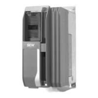
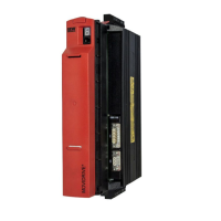
Overview of the MOVIDRIVE® compact system components and their arrangement.
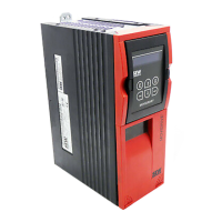
Details on the unit properties and control functionalities of the MOVIDRIVE® compact.
Technical data applicable to all MOVIDRIVE® compact drive inverters, regardless of type, version, size and power rating.
Dimension drawings for MOVIDRIVE® compact units of various sizes (0015 ... 0040-5A3 and 0015 ... 0037-2A3).
Lists all parameters with their setting range and factory settings for MOVIDRIVE® compact.
Detailed explanation of parameters, divided into 10 groups with factory settings indicated.
A guide to selecting the inverter based on drive properties and control process.
Guidance on selecting asynchronous AC motors for VFC operation, including voltage/frequency characteristics.
Recommendations for selecting asynchronous servomotors for CFC operation, including motor characteristics.
Explanation of how to determine the overload capacity of MOVIDRIVE® drive inverters based on various factors.
Details on the MOVILINK® profile for uniform data transmission between SEW inverters and automation equipment.
General safety precautions for handling and operating MOVIDRIVE® drive inverters.
Guidelines for the correct installation of MOVIDRIVE® compact drive inverters.
Instructions for performing electrical installation according to regulations and observing EMC guidelines.
Explanation of the unit designation system, nameplates, and the scope of delivery for MOVIDRIVE® units.
Detailed description of the connections and components for size 1 MCF/MCV/MCS4_A units.
General instructions for installing the basic unit, including tightening torques and mounting positions.
Wiring diagrams for the power section and brake connections of the basic unit.
Instructions for connecting motor encoders and external encoders to MOVIDRIVE® units.
Prerequisites and general steps for successful startup of MOVIDRIVE® compact drive inverters.
Detailed instructions for starting the motor, including analog setpoint selection and travel diagrams.
Procedure for configuring and starting up the inverter using the PROFIBUS-DP interface.
Steps for starting up the inverter with the INTERBUS interface module.
Explanation of the operating status displayed by the LED V1 on MC_40A units.
Explanation of the operating status displayed by the LEDs on MC_41A units (PROFIBUS-DP).
Explanation of the operating status displayed by the LEDs on MCH42A units (INTERBUS LWL).
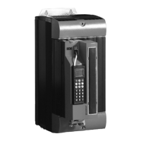
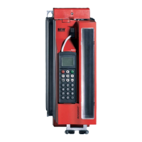
Information on the DBG11B keypad, its basic displays, copy function, and connection.
Details on the error memory (P080) and switch-off responses for MOVIDRIVE® compact.
A comprehensive list of fault codes, their designation, response, possible cause, and measure.
Information on how to send units in for repair and the required details to provide.
Alphabetical list of abbreviations used in the manual with their meanings.
Alphabetical index of topics covered in the manual for quick reference.