3
Device structure
Size 1
Operating Instructions – MOVIDRIVE
®
MDX60B/61B
19
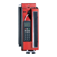
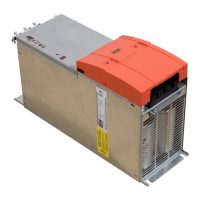
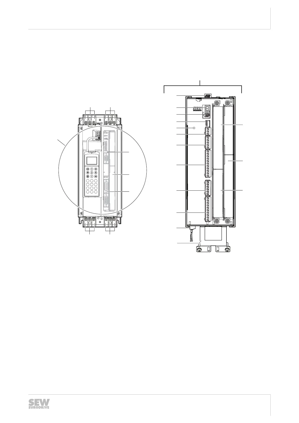
3.4 Size 1
MDX61B-5A3 (AC 400/500 V devices): 0015/0022/0030/0040
MDX61B-2A3 (AC 230 V devices): 0015/0022/0037
4
1 2 3
5 6
7 8 9
+/-
0
.
[2][1]
[6][7]
A
X16
X10
X13
X11
X12
XT
S11
S12
S13
S14
A
[8]
[9]
[10]
[11]
[12]
[13]
[14]
[15]
[16]
[17]
[18]
[19]
[4]
[3]
[5]
[3]
[4]
[5]
2205808267
[1] X1: Power supply connection 1/L1, 2/L2, 3/L3, separable
[2] X4: Connection for DC link coupling -U
Z
+U
Z
, separable
[3] Fieldbus slot
[4] Expansion slot
[5] Encoder slot
[6] X3: Braking resistor connection 8/+R, 9/–R and PE connection, separable
[7] X2: Motor connection 4/U, 5/V, 6/W and PE connection, separable
[8] Shield clamp for signal cables and PE connection
[9] X17: Signal terminal block for safety contacts of drive safety function STO
[10] X10: Signal terminal strip for digital outputs and TF/TH input
[11] X16: Signal terminal strip digital inputs and outputs
[12] X13: Signal terminal strip terminal strip for digital inputs and RS485 interface
[13] X11: Signal terminal strip for setpoint input AI1 and 10 V reference voltage
[14] X12: Signal terminal strip system bus (SBus)
23534850/EN – 11/2017
 Loading...