4
Installation
Connection and terminal description of the DEH11B (Hiperface) option
Operating Instructions – MOVIDRIVE
®
MDX60B/61B
122
4.17 Connection and terminal description of the DEH11B option (HIPERFACE
®
)
Connection
and
terminal
description
of the
DEH11B
(Hiperface)
option
4.17.1 Part number
Option HIPERFACE
®
encoder card type DEH11B: 08243107
INFORMATION
• The DEH11B option can be installed in MOVIDRIVE
®
MDX61B sizes 0–7. Only
SEW‑EURODRIVE may install or remove the DEH11B option for MOVIDRIVE
®
MDX61B size 0.
• The DEH11B option must be plugged into the encoder slot.
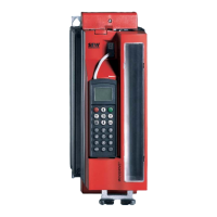
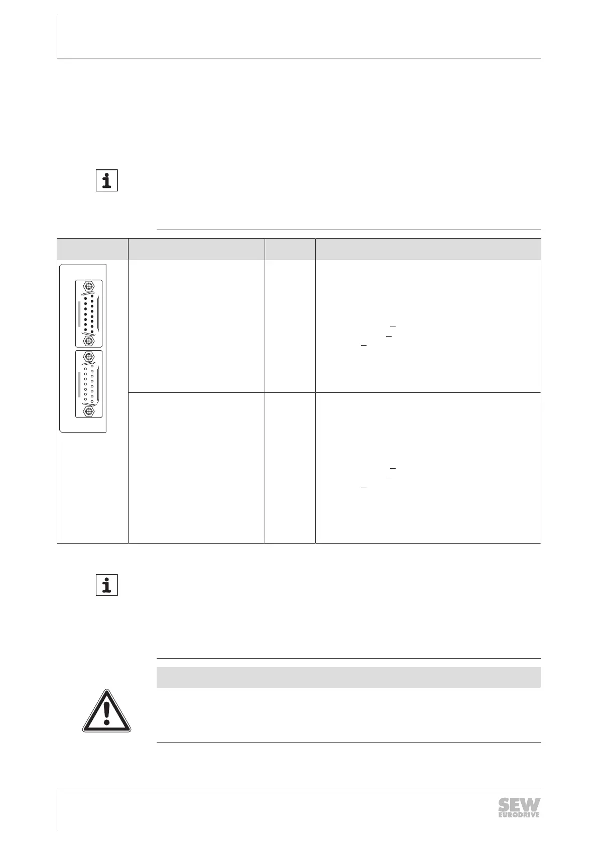
Front view of DE-
H11B
Description Terminal Function
X14: Input for external encoder or
output for incremental encoder simu-
lation
Number of pulses of the incremental
encoder simulation:
• As on X15
X14:1
X14:2
X14:3
X14:4
X14:5/6
X14:7
X14:8
X14:9
X14:10
X14:11
X14:12
X14:13/14
X14:15
(COS+) signal track A (K1)
(SIN+) signal track B (K2)
Signal track C (K0)
DATA+
Reserved
Switch between
Reference potential DGND
(COS–) Signal track A (K1)
(SIN–) Signal track B (K2)
Signal track C (K0)
DATA-
Reserved
DC+12 V (tolerance range DC 10.5 – 13 V)
(max. load X14:15 and X15:15 = DC 650mA)
X15: Motor encoder input X15:1
X15:2
X15:3
X15:4
X15:5
X15:6
X15:7
X15:8
X15:9
X15:10
X15:11
X15:12
X15:13
X15:14
X15:15
(COS+) signal track A (K1)
(SIN+) signal track B (K2)
Signal track C (K0)
DATA+
Reserved
Reference potential TF/TH/KTY–/PK
Reserved
Reference potential DGND
(COS–) Signal track A (K1)
(SIN–) Signal track B (K2)
Signal track C (K0)
DATA-
Reserved
TF/TH/KTY+/PK connection
DC+12V (tolerance range DC 10.5 – 13 V)
(max. load X14:15 and X15:15 = DC 650mA)
INFORMATION
• If X14 is used as an incremental encoder simulation output, the switch-over
(X14:7) must be jumpered with DGND (X14:8).
• The DC12V supply voltage from X14 and X15 is sufficient to operate encoders
by SEW‑EURODRIVE (except HTL encoders) with a DC 24 V supply voltage.
With all other encoders, check whether they can be connected to the DC 12 V
supply voltage.
NOTICE
Do not directly connect HTL encoders to X15 of option DEH11B.
Doing so can destroy the X15 (motor encoder input) on the DEH11B option.
• Use the DWE11/12 interface adapter
23534850/EN – 11/2017
 Loading...