Do you have a question about the SEW-Eurodrive MOVIAXIS MXP81A 503-00 Series and is the answer not in the manual?
| Protection Class | IP20 |
|---|---|
| Model | MXP81A |
| Communication Interfaces | EtherCAT, PROFINET, PROFIBUS |
| Cooling method | Air-cooled |
| Communication interface | EtherCAT, PROFINET, PROFIBUS |
| Relative humidity | 5% to 95% (non-condensing) |
| Power Supply | Three-phase |
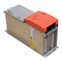
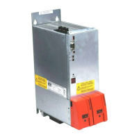
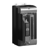
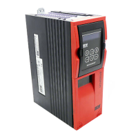
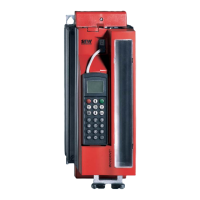
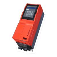
Modular multi-axis servo inverter system for drive and automation solutions.
Details the components that make up the MOVIAXIS® system.
Highlights the advantages and key features of the MOVIAXIS® system.
Covers different installation methods, module combinations, and communication options.
Explains the various technological functions and features of the units.
Covers integrated safety functions and concepts for secure operation.
Introduces the engineering software for startup, parameter setting, and diagnostics.
Explains the coding system for MOVIAXIS® basic units and options.
Detailed technical specifications for various MOVIAXIS® modules.
Details synchronous servomotors, including CMP, CMDV, and CMS series.
Details asynchronous servomotors, specifically the DRL series.
Lists compatible encoders for MOVIAXIS® systems.
Describes parameters related to displaying drive values.
Details parameters related to drive data, including controller settings.
Describes parameters related to communication settings.
Details parameters specific to encoder configuration and evaluation.
Explains parameters for Function Control Blocks (FCBs).
Introduces SEW Workbench software for compiling drive systems.
Provides essential information for planning MOVIAXIS® MX projects.
Guides on selecting appropriate servomotors for MOVIAXIS® systems.
Provides criteria and tables for selecting the correct braking resistor.
Defines the intended industrial and commercial use of MOVIAXIS® servo inverters.
Details electrical installation requirements, including safety and EMC compliance.
Covers operational safety, including monitoring and protection devices.
Provides guidelines for the mechanical installation of MOVIAXIS® units.
Covers essential electrical installation procedures and safety precautions.
Presents essential wiring diagrams for various connections.
Details terminal assignments for different MOVIAXIS® modules.
Details settings for power supply modules using the CAN-based system bus SBus.
Explains CAN-based application bus CAN2 connections and settings.
Introduces MOVITOOLS® MotionStudio for startup, parameter setting, and diagnostics.
Guides through the startup process for single-motor operation.
Details the startup procedure for multi-motor configurations.
Details operating displays and error codes specific to MXP power supply modules.
Provides a comprehensive list of operating displays and error codes for MXA axis modules.
Describes the procedure for removing and installing modules, including safety notes.