Do you have a question about the SEW MOVITRAC LTP series and is the answer not in the manual?
Explains how safety notes are structured using symbols and signal words.
Details forbidden applications and environmental considerations for the drive.
Provides instructions for disposing of electronic scrap and materials properly.
Covers general safety precautions during the installation and startup of the unit.
Details safety precautions for operating and servicing the drive unit.
Lists available input voltage ranges for different MOVITRAC® LTP units.
Explains the coding system used for product identification and ordering.
Details the overload capacity of the MOVITRAC® LTP units.
Lists various protection functions like over-current, over-voltage, and temperature.
Provides instructions for storing, mounting, and environmental considerations.
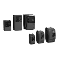
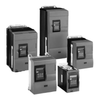
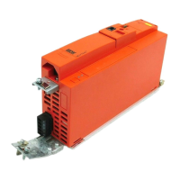
Presents detailed dimensions and fixing information for IP20/NEMA 1 housings.
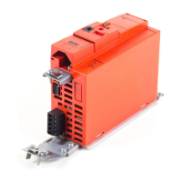
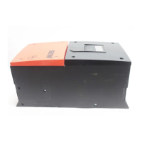
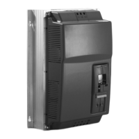
Provides detailed dimensions and fixing information for IP55/NEMA 12 housings.
Guidelines for mounting drives in IP20/NEMA 1 housings.
Specifies dimensions for vented housings.
Specifies dimensions for force-vented housings.
Covers safety and preparatory steps before electrical installation.
Instructions for accessing the front cover and helpcard.
Details connecting the drive and motor, including terminal box configurations.
Illustrates the power section wiring for the drive and motor connection.
Explains how to connect and configure motor thermal protection sensors.
Details the functions and connections of the signal terminal block.
Describes the RJ11 socket for RS-485 and MODBUS communication.
Explains the use of the optical interface for commissioning with a pocket PC.
Notes for installing the drive in compliance with UL standards.
UL compliance details for 380-480V units.
UL compliance details for 575V units.
Information on EMC immunity and emissions compliance.
Details the functions of the integrated keypad for drive operation and setup.
Guides through the initial setup and auto-tune process.
Explains how to operate the drive using external terminals and switches.
Instructions for operating the drive using the keypad for speed and direction control.
Identifies essential parameters for initial drive configuration.
Explains static and operational drive status mnemonics displayed on the unit.
Details how to access and interpret fault logs and troubleshooting steps.
Provides a chart for identifying and resolving common drive symptoms.
Lists fault messages, their explanations, and solutions.
Information on contacting service and required details for repair.
Explains how to navigate and reset parameters.
Describes how to view key operating variables in real-time.
Details the steps to enter and navigate parameter settings.
Lists and explains standard drive parameters with their ranges and defaults.
Details extended parameters for advanced configuration options.
Explains parameters for user feedback and PID control loops.
Parameters for advanced motor control modes like vector control.
Defines functions for digital inputs based on parameter settings.
Tables showing DI functions when P1-12 is set to Terminal mode.
Tables showing DI functions when P1-12 is set to Keypad mode.
Tables showing DI functions for User PID control mode.
Tables showing DI functions for MODBUS control mode.
Lists parameters available for real-time monitoring of drive status.
Details the specifications for MODBUS RTU implementation.
Explains the register map for MODBUS communication.
Describes the purpose of each register for MODBUS control.
Lists registers used for monitoring drive values via MODBUS.
Lists readable/writable parameters for MODBUS control.
Lists error codes for MODBUS communication.
Lists international standards the products comply with.
Details operational and storage environmental conditions.
Provides power and current specifications for different motor sizes.
Specifies output power and current for Size 1, 1-phase units.
Specifies output power and current for Size 2, 1-phase units.
Specifies output power and current for Size 3, 3-phase units.
Specifies output power and current for Size 4, 3-phase units.
Specifies output power and current for Size 5, 3-phase units.
Specifies output power and current for Size 6, 3-phase units.
Specifies output power and current for Size 2, 400V units.
Specifies output power and current for Size 3, 400V units.
Specifies output power and current for Size 4, 400V units.
Specifies output power and current for Size 5, 400V units.
Specifies output power and current for Size 6, 400V units.
Specifies output power and current for Size 2, 575V units.
Specifies output power and current for Size 3, 575V units.
Specifies output power and current for Size 4, 575V units.
Specifies output power and current for Size 5, 525V units.
Specifies output power and current for Size 6, 525V units.
| Category | DC Drives |
|---|---|
| Series | MOVITRAC LTP |
| Enclosure Rating | IP20 |
| Control Mode | V/f control |
| Protection Features | Overcurrent, overvoltage, undervoltage, short circuit, overtemperature |
| Communication Interface | CANopen |
| Ambient Temperature | 0 °C to +45 °C (derating may apply above 40°C) |