Do you have a question about the SEW MOVITRAC MC07B0220-503-4-00 and is the answer not in the manual?
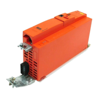
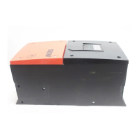
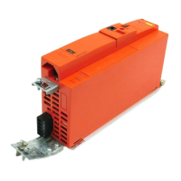
Presents a diagram and list of components and options for the MOVITRAC® B system.
Provides a table detailing unit types, power ratings, and sizes.
Details the wide voltage range, overload capacity, speed range, and unit properties.
Covers CE marking compliance and UL/CSA/GOST-R/C-Tick approvals.
Lists general technical specifications like temperature, climate class, and voltage tolerance.
Details electronics data including terminal functions, inputs, and outputs.
Provides detailed technical data for various MOVITRAC® B units and sizes.
Provides general information, types, and assignment of BW series braking resistors.
Explains HF output filters for smoothening output voltage and preventing interference.
Details fieldbus gateways, interfaces, and connection options.
Explains how to set parameters and provides a list of parameters with their descriptions.
Defines the source for the setpoint, such as analog input or fixed setpoints.
Enables or disables the PI controller and sets its operating mode (Normal/Inverted).
Sets the reference speed value for the drive control.
Activates speed monitoring to detect deviations from the setpoint or current limit.
Sets the basic operating mode of the inverter (VFC, V/f, hoist, etc.).
Defines the inverter's response to an external fault signal.
Outlines the step-by-step process for project planning of drive systems.
Lists available options like braking resistors and output chokes for simple applications.
Details planning considerations for specific applications like trolleys and hoists.
Provides recommendations and guidelines for selecting appropriate motors.
Describes overload capacity based on ambient temperature, voltage, and PWM frequency.
Guides the selection of braking resistors based on peak braking power and resistance.
Explains how to connect AC brakemotors and the function of brake rectifiers.
Covers mains connection, permitted voltage supply systems, and cable cross-sections.
Addresses EMC compliance, limit values, and installation measures.
Provides guidelines for installing and connecting HF output filters.
Illustrates the priority of operating states and the interrelation of control signals.
Describes the PI controller's function, parameterization, and setpoint selection.
Provides examples for external setpoint potentiometer, agitator, and trolley positioning.