Do you have a question about the SEW MOVITRAC MC07B0015-5A3-4-00/S0 and is the answer not in the manual?
States that adhering to operating instructions is a prerequisite for warranty claims and fault-free operation.
Defines SEW-EURODRIVE's liability exclusion for non-observance of operating instructions.
Details installation requirements, protection from strain, and handling of electronic components.
Outlines guidelines for electrical installation, EMC compliance, and grounding.
Provides safety notes for operating systems with integrated frequency inverters.
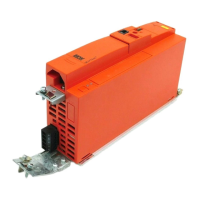
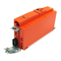
Describes MOVITRAC® B as an AC drive with inverter technology for optimizing system concepts.
Presents a system overview of MOVITRAC® B, illustrating various components and connections.
Details the functions and features of MOVITRAC® B inverters, including voltage range and overload capacity.
Describes the MOVITOOLS® MotionStudio program and its capabilities for SEW inverters.
Covers CE marking, UL approval, CSA, and GOST-R certificates for MOVITRAC® B units.
Lists general technical specifications for MOVITRAC® B inverters, including temperature and climate class.
Provides detailed electronics data for MOVITRAC® B, including terminal functions and specifications.
Presents a comprehensive overview of technical data for MOVITRAC® B series units.
Provides general information on BW series braking resistors and PTC braking resistors.
Covers fieldbus gateways for connecting to SEW SBus and automation systems.
Introduces the MOVI-PLC® controller, a user-programmable device compliant with IEC 61131-3.
Explains how to set MOVITRAC® B parameters using keypad or software.
Defines fundamental control properties and automatic inverter functions.
Details unit functions including setup, language selection, and factory settings.
Outlines the schematic procedure for project planning, from clarification to component selection.
Details application planning for trolleys and hoists, including thermal considerations.
Provides guidance on motor selection, including basic recommendations and voltage-frequency curves.
Describes overload capacity depending on ambient temperature, voltage, and PWM frequency.
Guides on selecting braking resistors based on peak braking power and DC link voltage.
Covers mains contactors, input fuses, and permitted voltage supply systems.
Covers multi-motor and group drives, including motor currents, cable length, and output filters.
Explains EMC product standards and recommendations for EMC-compliant installation.
Discusses interference emission testing and recommended measures for EMC compliance.
Provides instructions for using HF output filters, including installation and connection.
Covers electronics cables, signal generation, and external voltage supply.
Illustrates operating state priorities and interrelations between control signals.
Explains the interrelation between control signals and their effect on drive control.
Details the PI controller for temperature, pressure, or other applications.
Explains how to parameterize the PI controller, including activation and settings.
Describes possible setpoint sources and how to select them using parameter P100.
Details how to determine the direction of rotation and control the inverter.
Presents application examples, including external setpoint potentiometer and setpoint value processing.
Provides general installation notes, including mounting front options and safety compliance.
Details EMC-compliant installation practices for cables, shielding, and grounding.
Covers line protection, earth-leakage circuit breakers, and PE mains connection requirements.
Explains the installation of optional power components like line chokes and filters.
Provides guidelines for UL compliant installation, including cable types and tightening torques.
Details the scope of delivery for loose items and their installation procedures.
Shows the wiring diagram for connecting the inverter, motor, and optional components.
Illustrates connecting braking resistors BW.. / BW..-T / BW..-P to terminals X3 / X2.
Explains how to enhance basic units with FSC11B and FIO11B modules.
Provides instructions for mounting and connecting the MBG11A speed control module.
Provides a brief description of the startup process for MOVITRAC® B frequency inverters.
Offers general instructions and prerequisites for successful drive startup.
Describes the FBG11B keypad, its key arrangement, and functions.
Explains basic operation of the FBG11B keypad, including menu navigation and parameter changes.
Covers external setpoint selection methods, including terminals, serial interface, and potentiometers.
Guides through the startup process using the FBG11B keypad, including motor selection and operating modes.
Provides instructions for startup using the DBG60B keypad, covering motor type and settings.
Provides instructions for starting the motor, including analog setpoint specification and fixed setpoints.
Lists all parameters, their range, factory settings, and FBG keypad access.
Explains data backup procedures using FBG11B, DBG60B, UBP11A, and MOVITOOLS®.
Describes status displays on the FBG11B keypad, including drive status and binary I/O.
Details basic displays and information messages on the DBG60B keypad.
Provides information about the unit, including fault memory and switch-off responses.
Details the three switch-off responses depending on the fault type.
Provides a comprehensive list of faults, their designation, response, cause, and measure.
Offers contact information for SEW electronics service, including hotline and repair procedures.