Do you have a question about the SEW MOVITRAC MC07B0011-5A3-4-00/S0 and is the answer not in the manual?
| Model | MC07B0011-5A3-4-00/S0 |
|---|---|
| Power Rating | 1.1 kW |
| Output Power | 1.1 kW |
| Output Current | 2.5 A |
| Phase | 3-phase |
| Frequency Range | 0-400 Hz |
| Protection Class | IP20 |
| Type | MOVITRAC |
| Input Voltage | 380-480 V |
| Output Voltage | 0-480 V |
| Control Method | Vector control |
| Communication Interface | RS-485 |
| Cooling Method | Air cooling |
Basic safety notes intended to prevent injury and property damage, emphasizing operator responsibility.
Specifies that only qualified electricians should handle the units, adhering to relevant standards.
Defines frequency inverters as components for electrical systems and machines, outlining installation and startup conditions.
Information on electrical installation, national guidelines, EMC-compliant practices, and grounding requirements.
Table summarizing MOVITRAC® B types, motor power, output current, and size based on power supply connection.
Details on MOVITRAC® B frequency inverters' features, including voltage range, overload capacity, and speed range.
Information on conformity with directives and approvals like CE, UL, CSA, GOST-R, and C-Tick.
Provides key technical specifications applicable to all MOVITRAC® B inverters, regardless of size or power.
Detailed electronic data including terminal functions, setpoint inputs, binary I/O, and auxiliary voltage.
Specific technical data tables for various MOVITRAC® B models based on power supply and size.
General information, PTC braking resistors, flat design, wire resistors, and grid resistors.
Technical data and dimension drawings for HF output filters, used to smoothen inverter output voltage.
Information on fieldbus gateways and interfaces for connecting MOVITRAC® B to automation systems.
Information on MOVI-PLC® controller unit versions and description.
Details on parameter settings, including how to set them via keypad, PC, or copying.
Parameter list covers process data parameter setting and serial communication.
Parameter list covers serial communication (SBus protocol, address, baud rate, CANopen address).
Step-by-step process for project planning, covering clarification, calculation, and selection of components.
Recommendations for motor selection, including basic guidelines and voltage-frequency characteristic curves.
Information on inverter overload capacity depending on ambient temperature, voltage, and PWM frequency.
Guidelines for selecting braking resistors, including parallel connection, peak braking power, and load capacity.
Guidelines for mains and motor connection, including permitted voltage supply systems and contactors.
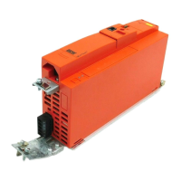
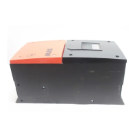
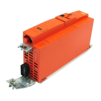
Detailed unit design and connection points for MOVITRAC® B sizes 0XS, 0S, and 0L.
Detailed unit design and connection points for MOVITRAC® B sizes 1, 2S, and 2.
Detailed unit design and connection points for MOVITRAC® B size 3.
Detailed unit design and connection points for MOVITRAC® B sizes 4 and 5.
General notes and guidelines for installing MOVITRAC® B units, including mounting front options and tools.
Schematic wiring diagrams for power supply, signal terminals, and motor connections.
Overview of the startup process, including connecting motor, braking resistor, and signal terminals.
Step-by-step guide for startup using the FBG11B keypad, covering motor selection and operating mode.
Procedure for startup using the DBG60B keypad, including required data and language selection.
Comprehensive list of parameters with index, name, range, factory setting, and display options.
Details on unit information, including fault memory and switch-off responses.
Comprehensive list of faults, their designations, responses, possible causes, and measures.