High-Power Stereo Class-D Audio Power Amplifier
SGM4703 with Adjustable Power Limit and Automatic Level Control
22
DECEMBER 2022
SG Micro Corp
www.sg-micro.com
APPLICATION INFORMATION (continued)
Single-Side-Modulation (SSM)
The SSM scheme alters the DSM scheme in order to
achieve higher efficiency with a slight penalty in THD
degradation and more attention required for the
selection of the output filter. With SSM scheme, the
audio outputs operate with less than 10% modulation
during an idle condition. When an audio signal is
applied, one output will decrease and another one will
increase. The decreasing output signal will quickly rail
to ground at which point all the audio modulation takes
place through the rising output. The result is that only
one output is switching during a majority of the audio
cycle. Efficiency is improved with SSM scheme due to
the reduction of switching losses. The THD penalty with
SSM scheme is minimized by the on-chip linear
feedback loop.
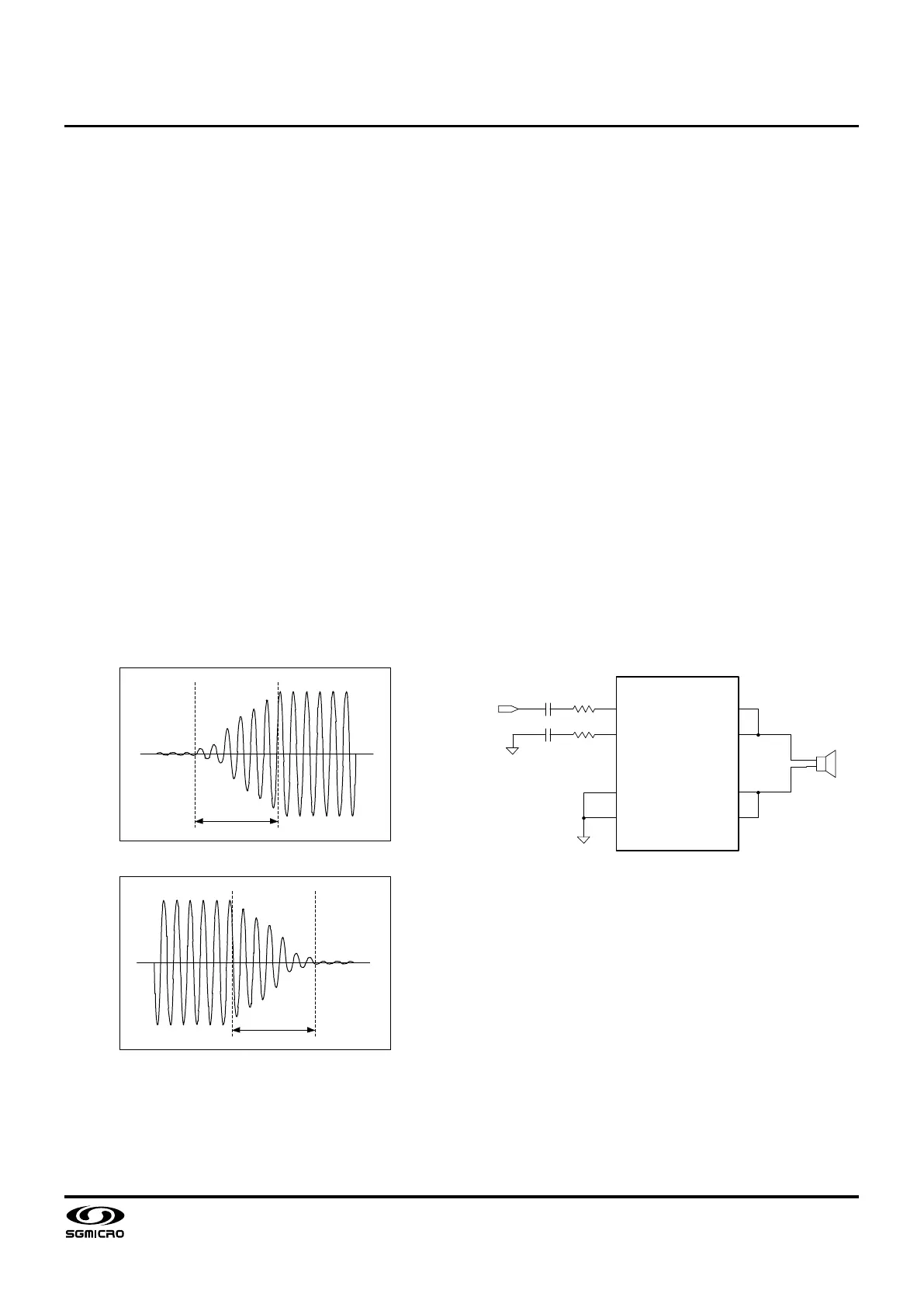
Volume Fade-In and Fade-Out
The SGM4703 features volume fade-in and fade-out to
reduce intermittent sound and eliminate uncomfortable
hearing experience during the transitions when the
device enters or exits the normal operation. Figure 9
and Figure 10 show the audio output waveforms during
fade-in and fade-out respectively.
Figure 9. Fade-In Waveform
Figure 10. Fade-Out Waveform
PBTL Configuration (Mono Mode)
The SGM4703 features an optional mono mode that
allows the left and right channels to operate in parallel
BTL configuration. To operate the SGM4703 in mono
mode, connect the INNR and INPR pins (pin 11 and 12)
directly to ground (no decoupling capacitors). In mono
mode, as shown in Figure 11, an audio input signal
applied to the left channel (pin 3 and 4) is routed to the
H-bridge of both channels. Note that the mono mode is
intended to be configured strictly by the hardware
connection. Leaving either INNR or INPR pin
unconnected while the audio outputs VOPL/R and
VONL/R are wired together in PBTL configuration can
trigger an over-current or thermal overload protection or
both. The mono mode is configured by the following
arrangement:
● Connect INPR and INNR pins directly to ground (no
decoupling capacitors).
● Connect VOPL to VONL together as one terminal of
the speaker and connect VOPR to VONR together
as the other terminal of the speaker. Use heavy
PCB traces as close as possible to the device.
● Place the speaker between the left and
right-channel outputs.
● Apply an audio signal to the left-channel inputs
(INPL and INNL pins).
Figure 11. PBTL Configuration for Mono Applications
Click-and-Pop Suppression
The SGM4703 features comprehensive click-and-pop
suppression. During startup, the click-and-pop
suppression circuitry reduces any audible transients
internal to the device. When entering into shutdown,
the differential audio outputs VOPL/R and VONL/R
ramp down to ground simultaneously.
PSRR Enhancement
Without a dedicated pin for the common-mode voltage
bias and an external holding capacitor onto the pin, the
SGM4703 achieves a PSRR, 80dB at 1kHz with SSM
scheme.
INPL
INNL
INNR
INPR
VOPR
VONR
VONL
VOPL
LS
SPEAKER
R
INE
R
INE
C
IN
C
IN
IN
 Loading...