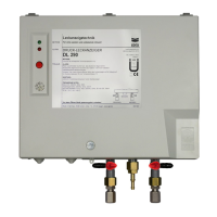
1. Subject
ZD … "Additional pressure switch" for applications in which this equipment is required,
e.g. when certain piping lengths are exceeded (see approval for double-walled pipes).
2. Field of application
(1) ZD … can be installed outdoors
(2) Components in contact with the conveyed product are made of V4A, PE and PP
(3) Pressure-resistant up to 25 bar
3. Electrical connections
Connect terminals 10 / 11 of the VL-HFw2 and terminals 21 / 22 of the VLR …/E to the
terminals with the same names on the ZD ….
4. Start-up
After installation and electrical connections are complete:
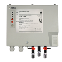
4.1. In conjunction with the VL-HFw2 leak detector
Connect the ZD to terminals 10 and 11 of leak detector VL-HFw2.
(1) Press button on the ZD (so that it latches).
(2) Press start-up button on the VL-HFw2 and generate underpressure in the system.
(3) After the operating underpressure is reached, press the start-up button again (also see
documentation for the above-mentioned leak detector).
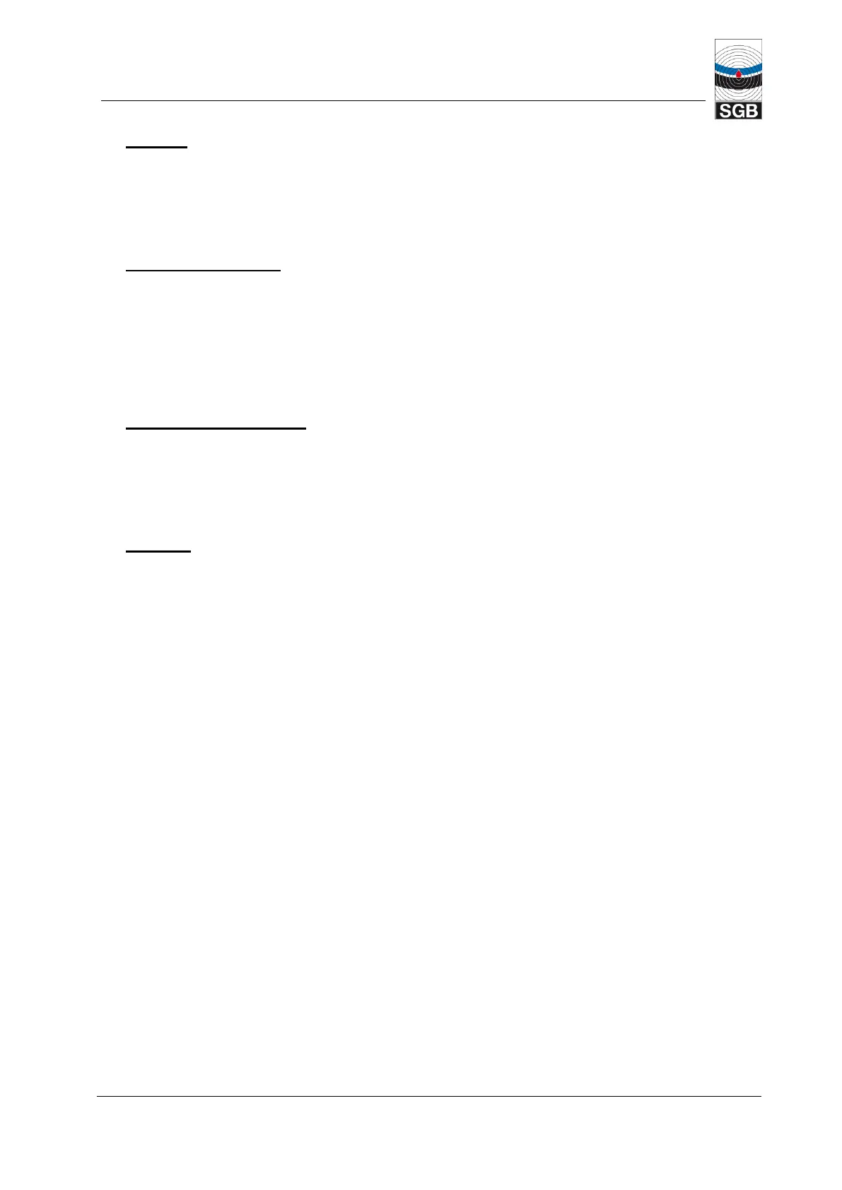
4.2. In conjunction with the VLR …/E leak detector
Connect the ZD as a "sensor" to terminals 21 and 22 in leak detector VLR …/E.
4.2.1 VLR …/E WITHOUT connected solenoid valve
(1) Do not press button (not latched).
(2) Generate operating underpressure in the system.
(3) When the switching value "Alarm OFF" of the ZD … is reached, the "Sensor alarm" on the
leak detector is cleared.