EasyManua.ls Logo

Sharp 19J-M100 User Manual

Sharp 19J-M100
29 pages
To Next Page IconTo Next Page
Page #1 background imageLoading...
Page #1 background image
1
19J-M100/100S/150/20J-M100
CJ19M10/CJ20M10 / 20MJ10
SERVICE MANUAL
Page
æ ELECTRICAL SPECIFICATIONS............................................................................................1
æ IMPORTANT SERVICE SAFETY PRECAUTION ...................................................................2
æ LOCATION OF USER'S CONTROL ........................................................................................6
æ INSTALLATION AND SERVICE INSTRUCTIONS...................................................................7
æ CHASSIS LAYOUT ............................................................................................................... 13
æ BLOCK DIAGRAM ................................................................................................................ 14
æ SCHEMATIC DIAGRAMS .....................................................................................................15
æ PRINTED WIRING BOARD ASSEMBLIES ...........................................................................21
æ REPLACEMENT PARTS LIST ..............................................................................................27
æ PACKING OF THE SET ........................................................................................................ 35
CONTENTS
In the interests of user-safety (Required by safety regulations in some countries ) the set should be restored to its
original condition and only parts identical to those specified should be used.
POWER INPUT ........................... 120 V AC 60 Hz
POWER RATING .......................................... 84 W
PICTURE SIZE............... 19":1194cm
2
(185sq inch)
....................................20":1240cm
2
(192sq inch)
CONVERGENCE .................................... Magnetic
SWEEP DEFLECTION............................ Magnetic
FOCUS....................... Hi-Bi-Potential Electrostatic
INTERMEDIATE FREQUENCIES
Picture IF Carrier Frequency ............. 45.75 MHz
Sound IF Carrier Frequency .............. 41.25 MHz
Color Sub-Carrier Frequency ............ 42.17 MHz
(Nominal)
AUDIO POWER
ELECTRICAL SPECIFICATIONS
COLOR TELEVISION
Chassis No. SN-70
19J-M100/19J-M100S
19J-M150/CJ19M10
20J-M100/CJ20M10/20MJ10
Specifications are subject to change without prior
notice.
OUTPUT RATING ........ 0.9W (at 10% distortion)
SPEAKER
SIZE ................................................ 8cm(Round)
VOICE COIL IMPEDANCE ....... 8ohm at 400 Hz
ANTENNA INPUT IMPEDANCE
VHF/UHF............................ 75 ohm Unbalanced
TUNING RANGES
VHF-Channels....................................... 2thru 13
UHF-Channels .................................... 14thru 69
CATV Channels ................................... 1thru 125
USA: (EIA, Channel Plan)
MODELS
9CH
8
V
O
L+
VIDEO IN AUDIO
POWER
19J-M100/150/100S
CJ19M10
?CH
>
–VOL
+
VIDEO IN AUDIO
POWER
20J-M100
CJ20M10
SHARP ELECTRONICS CORPORATION
Service Headquarters: Sharp Plaza, Mahwah, New Jersey 07430-2135
SHARP ELECTRONICS OF CANADA LTD.
335 Britannia Road East Mississauga, Ontario L4Z 1W9 Canada
SHARP CORPORATION
S67A419J-M100
Question and Answer IconNeed help?

Do you have a question about the Sharp 19J-M100 and is the answer not in the manual?

Sharp 19J-M100 Specifications

General IconGeneral
Screen Size19 inches
Aspect Ratio16:9
Resolution1366 x 768
HDMI Ports1
USB Ports1
Display TypeLCD

Summary

ELECTRICAL SPECIFICATIONS

POWER INPUT

Input power requirements and frequency.

POWER RATING

Power consumption during operation.

PICTURE SIZE

Diagonal screen dimensions and viewable area.

CONVERGENCE

Magnetic convergence method used for picture alignment.

SWEEP DEFLECTION

Magnetic sweep deflection system for picture display.

FOCUS

Hi-Bi-Potential Electrostatic focus method.

INTERMEDIATE FREQUENCIES

Carrier frequencies for IF, sound, and color signals.

OUTPUT RATING

Speaker output power with distortion level.

SPEAKER

Speaker size and impedance specifications.

VOICE COIL IMPEDANCE

Impedance of the speaker's voice coil.

ANTENNA INPUT IMPEDANCE

Antenna connection impedance for VHF/UHF signals.

TUNING RANGES

Channel ranges for VHF, UHF, and CATV reception.

IMPORTANT SERVICE SAFETY PRECAUTION

WARNING

General warnings for safe service procedures and potential hazards.

X-RADIATION AND HIGH VOLTAGE LIMITS

Guidelines for managing X-radiation and high voltage risks during servicing.

BEFORE RETURNING THE RECEIVER (Fire & Shock Hazard)

Safety checks before returning the unit to the customer.

SAFETY NOTICE

General safety notices regarding replacement parts and hazards.

INSTALLATION AND SERVICE INSTRUCTIONS

CIRCUIT PROTECTION

Details on the receiver's fuse and circuit protection.

X-RADIATION PROTECTOR CIRCUIT TEST

Procedure to test the X-radiation protection circuit.

HIGH VOLTAGE CHECK

Method for checking and verifying high voltage levels.

LOCATION OF USER'S CONTROL

Front Panel Controls

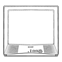
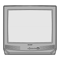
Identification of controls on the TV's front panel.

BASIC REMOTE CONTROL FUNCTIONS

Explanation of functions for the remote control.

ADJUSTMENT PROCEDURES

VCO Adjustment

Procedure to adjust the Voltage Controlled Oscillator.

RF AGC Adjustment

Procedure to adjust the Radio Frequency Automatic Gain Control.

Screen adjustment

Procedure for adjusting screen parameters like color and brightness.

White balance adjustment

Procedure to adjust white balance for accurate color reproduction.

Sub-picture adjustment

Procedure to adjust picture contrast settings.

Sub-Tint Adjustment

Procedure to adjust color tint for natural flesh tones.

Sub-color adjustment

Procedure to adjust color level for normal color output.

Sub-brightness adjustment

Procedure to adjust brightness level for optimal display.

Vertical-size adjustment

Procedure to adjust the vertical picture size.

Vertical phase adjustment

Procedure to adjust vertical phase for picture centering.

Horizontal position adjustment

Procedure to adjust horizontal picture position.

Caption position adjustment (horizontal)

Procedure to adjust the horizontal position of closed captions.

3.58MHz trap adjustment

Procedure to adjust the 3.58MHz trap for normal viewing.

Sharpness and Audio balance adjustments

Procedures for adjusting sharpness and audio balance.

CHASSIS LAYOUT

BLOCK DIAGRAM

DESCRIPTION OF SCHEMATIC DIAGRAM

WAVEFORMS

Measurement conditions and examples of signal waveforms.

SCHEMATIC DIAGRAM :CRT Unit

Schematic diagram for the CRT unit.

PRINTED WIRING BOARD ASSEMBLIES

PARTS LIST

PARTS REPLACEMENT

Information on safety characteristics of replacement parts.

HOW TO ORDER REPLACEMENT PARTS

Instructions on how to order replacement parts correctly.

PICTURE TUBE

List of replacement picture tubes.

TUNER

List of replacement tuner components.

INTEGRATED CIRCUITS

List of replacement integrated circuits.

TRANSISTORS

List of replacement transistors.

PRINTED WIRING BOARD ASSEMBLYS

Part numbers for printed wiring board assemblies.

PACKAGED CIRCUITS

List of replacement packaged circuits.

FILTERS

List of replacement filter components.

COILS

List of replacement coil components.

TRANSFORMERS

List of replacement transformer components.

CAPACITORS

List of replacement capacitor components.

RESISTORS

List of replacement resistor components.

DIODES

List of replacement diode components.

MISCELLANEOUS PARTS

List of various miscellaneous replacement parts.

CABINET PARTS

List of replacement cabinet components.

SUPPLIED ACCESORRIES

List of supplied accessories with the unit.

PACKING PARTS

List of packing materials not for replacement.

PACKING OF THE SET

Related product manuals