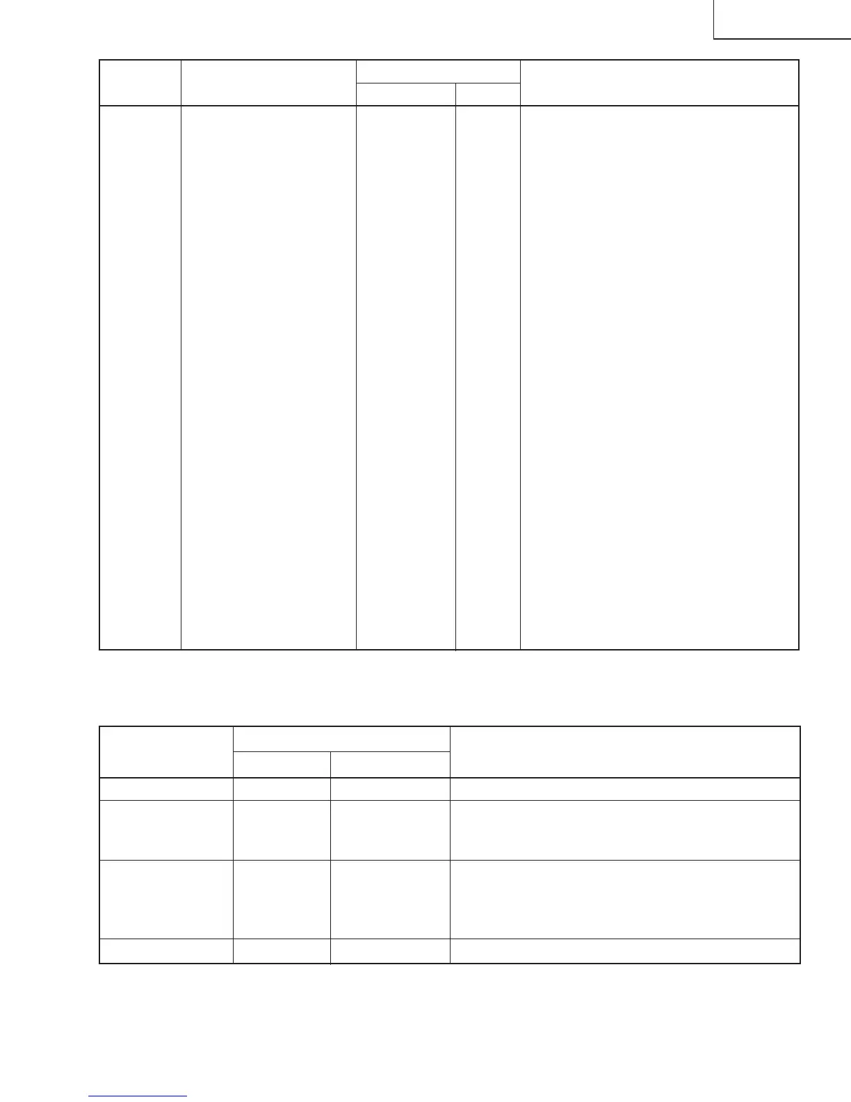
7
SERVICE
NUMBER
DATA
ADJUSTMENT CONTENTS
ADJUSTMENT ITEM
RANGE
INITIAL VALUE
S01 PICTURE 55 00-7F
S02 TINT 46 00-7F
S03 COLOR 32 00-7F
S04 BRIGHTNESS 40 00-7F
S05 SHARPNESS 28 00-3F Must be set to "24"
S06 VERTICAL PHASE 00 00-07 Must be set to "00" ~ "03"
S07 HORIZONTAL PHASE 12 00-1F
S08 RF-AGC 23 00-3F
S09 VERTICAL AMP 20 00-3F
S10 VCO 2C 00-7F
S11 R CUT-OFF 00 00-FF
S12 G CUT -OFF 00 00-FF
S13 B CUT-OFF 00 00-FF
S14 G GAIN 7F 00-FF
S15 B GAIN 7F 00-FF
S16 TRAP(3.58MHz) 00 00 or 01 Must be set to "00"
S17 BALANCE 20 00-3F Must be set to "20"
S18 C.C.POSITION 17 00-7F
S19 Y-MUTE 00 00,01,03
"00" = NORMAL, "01" = No Y, "03" = No VERTICAL
S20 ENERGY SAVE OFFSET 20 00-3F Must be set to "23"
S21 D.D.E. OFFSET 03 00-1F Must be set to "03"
S22 OSD SETUP 00 00-03 Must be set to "00"
S23 TUNER SETUP 00 00-01 Must be set to "00"
OP OPTION 30 00-FF Must be set to "02"
NECESSARY
UNNECESSARY
ADJUSTMENT
NOTES
PART REPLACED
IC2001
IC2101 X
CRT X
IC201
X
X
Data is stored in IC2101.
The adjustment is needed to compensate for characteristics
of parts including IC201.
Holding down both the CH-up/down buttons on the TV set in
the service mode for more than 2 seconds will automatically
write the above initial values into IC2101.
Adjust items related to picture tube only.
Table - A
Holding down both the CH-up/down buttons on the TV set at service mode for more than 2 seconds will automatically
write the above initial values into IC2101.
Table - B
20MU11