21F-PD250 / 21F-PT220 / 21F-PA18 / 21F-PA18(B)
3 – 15
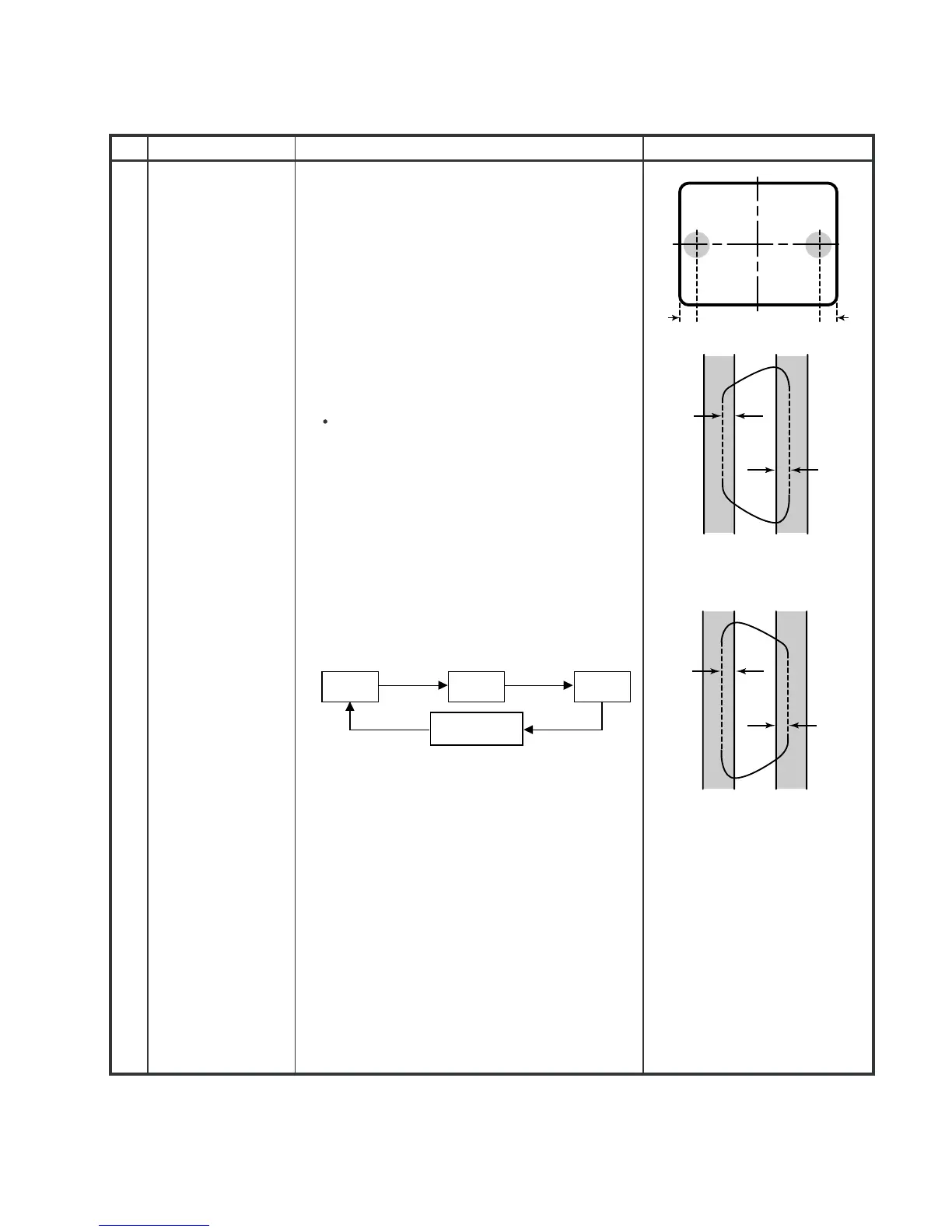
2. PURITY ADJUSTMENT
No.
Adjustment point
Adjustment procedure/conditions Waveform and others
1. Receive the GREEN-ONLY signal. Adjust the
beam current to ~700 µA .
2. Degauss the CRT enough with the degausing coil.
Note: Follow the Job Instruction Sheet to adjust
the magnetic field.
(Reference: page 3-5)
3. Maintain the purity magnet at the zero magnetic
field and keep the static convergence roughly
adjusted.
4. Observe the points a, b,as shown in Fig. 1-1
through the microscope. Adjust the landings to A
rank requirement.
5. Orient the raster rotation to 0 eastward.
6. Tighten up the deflection coil screws.
Tightening torque: 108 ± 20 N (11kgf ± 2 kgf)
7. Make sure the CRT corners landing meet the A
rank requirements. If not, stick the magnet sheet
to correct it.
Note: This adjustment must be done after
warming up the unit for 30 minutes or
longer with a beam current over 700
µ
A.
Note:
* For the following colours press R/C RGB(Hex 7E)
key to change.
PURITY ADJ.
(No need if used
ITC CRT)
1
a
b
A
B
A
30mm 30mm
B
A=B
A=B
Rank "A"
(on the right of the CRT)
Rank "A"
(on the left of the CRT)
Fig. 1-1
Fig. 1-2
Fig. 1-3
* Press R/C RGB key for 1 sec-
ond in NORMAL MODE, the
colour will change to RGB
mono colour mode.
Signal-colour
screen cleared
GREEN
ONLY
BLUE
ONLY
RED
ONLY
Set to service mode by remote con-
troller then press factory process R/C
RGB key to change to RGB mono col-
our mode.