21F-PD250 / 21F-PT220 / 21F-PA18 / 21F-PA18(B)
3 – 19
No.
Adjustment point
Adjustment procedure/conditions Waveform and others
SUB-
BRIGHTNESS
(to be done
after screen,
white balance
adj)
(12C BUS
CONTROL)
3
SUB-
CONTRAST
(to be done
after screen,
white balance
adj,
sub-bright-
ness adj)
(I
2
CBUS
CONTROL)
4
1) Receive the “Monoscope Pattern” signal.
2) Press R/C to set Picture NORMAL condition.
3) Connect the DC miliammeter between TP 603
(+)&TP602(-).
(Full Scale: 3mA Range)
4) Beam current must be within 1100
±
100
µ
A.
Beam Current
Check
5
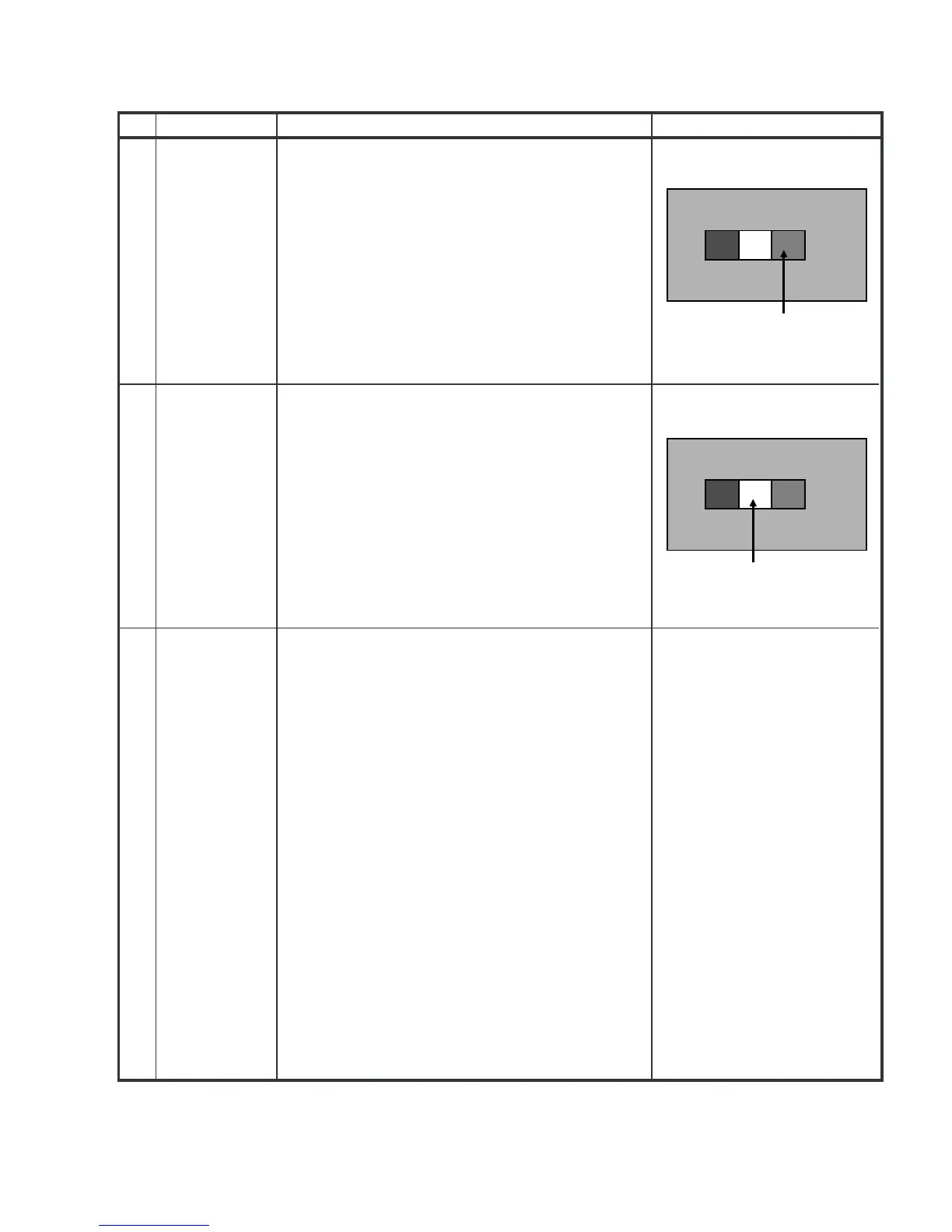
Dark White
WINDOW PATTERN SIGNAL
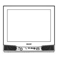
White
WINDOW PATTERN SIGNAL
1) In Window Pattern Signal condition.
Using Minolta Color Analyzer CA-100, let the
gun point at Dark White position (as attach
drawing), adjust V06 Bus data until
LUMINANCEY=3±0.5cd/m2.
2)
1) In Window Pattern Signal condition.
Using Minolta Color Analyzer CA-100, let the
gun point at White position (as attach drawing),
adjust V04 Bus data until LUMINANCE Y = 160
±10cd/m2
2)