PIF/AFT/SIF/AGC
ADJUSTMENT
(Continued)
AFT COIL ROUOGH ADJUSTMENT:
T1201
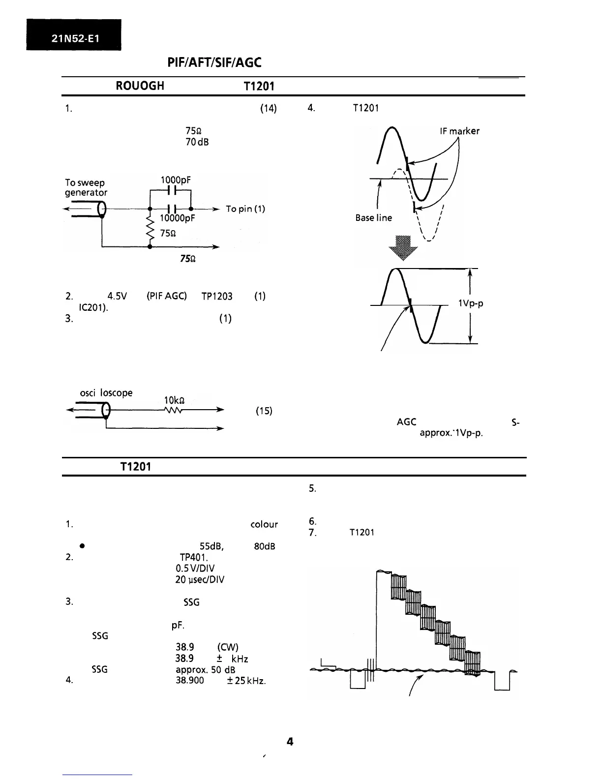
1.
Connect sweep generator’s output to pin
(14)
of IF unit.
l
Probe in use:
750 DC cut probe
l
Sweep output level:
70
dB
4.
Adjust T1201 to align the marker with the
base line.
,ker
2.
3.
Connection Diagram of
75Q
DC Cut Probe.
Apply
4.5V
DC
(PIF
AGC)
to TP1203 (pin
(1)
of
IC201).
Connect response lead to pin
(1)
of IF unit.
(The response lead should be a direct probe
with a 1 Ok ohm resistor included.)
l
Tune off AFT Mute.
t
1VP-P
/fil!!!A
Align the IF marker with the
base line.
To
osci
I
loscope
*
To pin
(15)
l
Adjust the sweep generator’s sweep range
to obtain normal S-curve on the oscilloscope
screen.
l Adjust the IF
AGC
voltage so that the
S-
curve’s amplitude be approx.‘lVp-p.
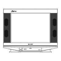
AFT COIL: T1201
Before this adjustment, the AFT coil
(rough adjustment) must have been
completed.
1.
Receive “PAL COLOUR BAR” signal with
colour
bar generator.
e
Signal strength: Over
55dB,
Below
80dB
2.
Connect oscilloscope to
TP401.
l
Oscilloscope range:
0.5
V/DIV
l
Sweep time:
20
PsedDlV
l
Synchronization:
Horizontal sync.
3.
Connect the output of
SSG
(Standard Signal
Generator) to the tuner IF output terminal
across a capacitor of 1
pF.
l
SSG
output frequency:
38.9
MHz
(CW)
38.9
MHz
+
5 kHz
l
SSG
output level:
approx.
50
dB
4.
Adjustment error:
38.900
MHz
+
25
kHz.
* When the preset switch is set at U or V
position, AFT is turned off.
/
.
5.
Set the preset switch at V position and adjust
FINE button (Up or Down) of tuning control so
that the output waveform suffers no beating.
6.
Set the preset switch at NORMAL position.
7.
Adjust
T1201
so that no beating is caused at
the output waveform.
Finely adjust to make zero the beating