SERVICE ADJUSTMENT
PIF/AFT/SIF/AGC
ADJUSTMENT
TUNER
IFT
COILS
The tuner has been factory preset (no
adjustment is needed).
1.
Set
Vr
voltage at
5V
in
VH
band.
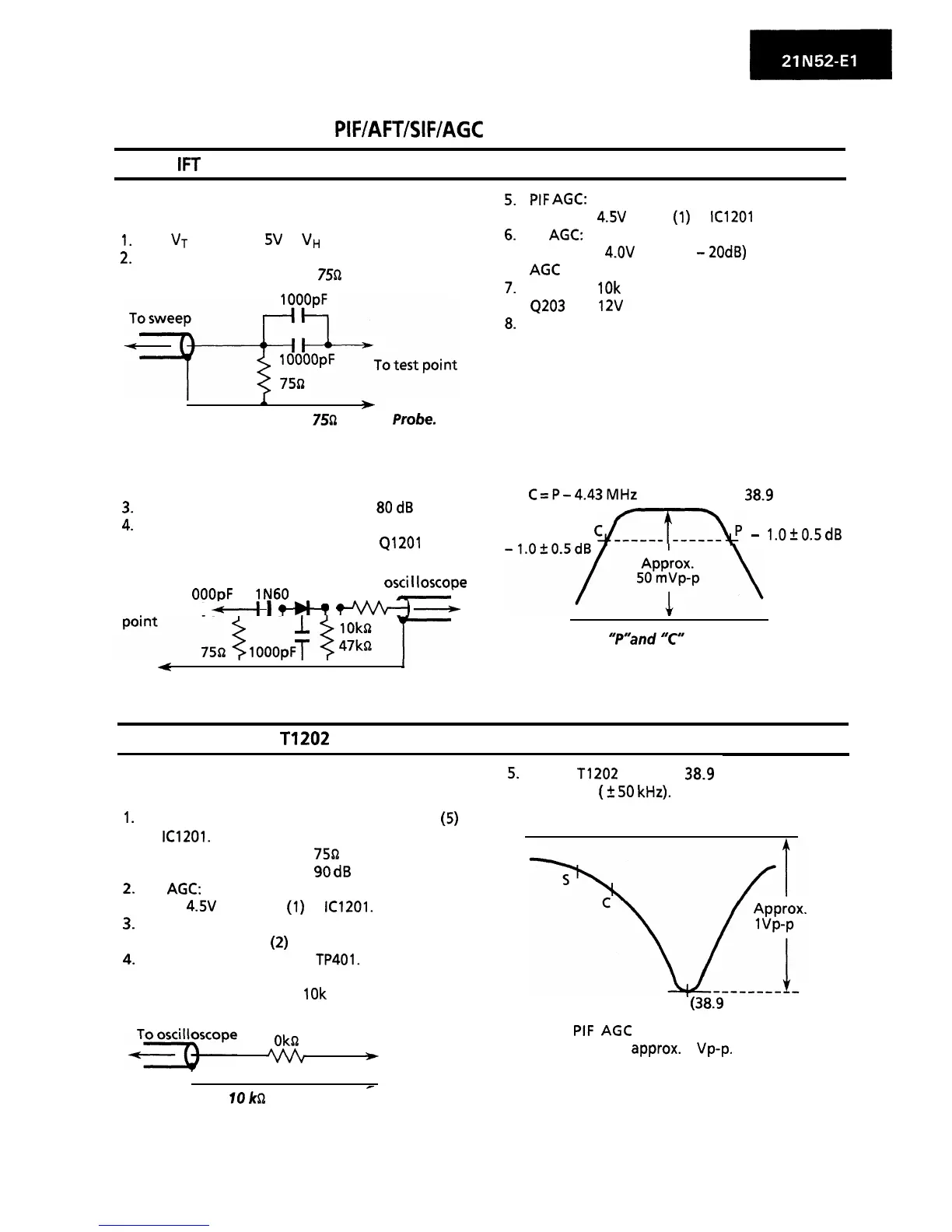
2.
Connect sweep generator’s output to the test
point of tuner, by using a
7552
DC cut probe.
I
A
w
Connection Diagram of
75G
DC Cut
Probe.
* NOTE:
The sweep generator’s probe should be
grounded closely to the tuner test point.
3.
Output level of sweep generator:
80
dB
4.
Connect response lead (low impedance probe
with detector) to the collector of
Q1201
(in IF
unit).
To
osci
I
loscope
To
1
OOOpF
lN60
test
4-l
I
?
U-
;:
*
4
A A A
Connection Diagram of Low Impedance Probe
(with Detector).
5.
6.
7.
8.
PIF
AGC:
Apply DC
4.5V
to pin
(1)
of
IC1201
(in IF unit).
RF
AGC:
Apply DC
4.OV
(about,
-2OdB)
to the tuner
AGC
terminal.
Connect
10k
ohm resistor between base of
4203
and
12V
line.
Adjust the tuner IF coils to obtain the
waveform as shown figure below.
NOTE:
For the adjustment, keep the tuner covered
with its lid.
C=P-4.43MHz
P = 38.9 MHz
cLx&
-
l.O+O.SdB
Adjust so that “Plland
“C”
are at the same /eve/.
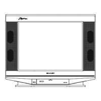
P-DETECTOR COIL:
T1202
This coil (in IF unit) has been factory
5.
Adjust T1202 so that 38.9 MHz signal is at
preset (no adjustment is needed).
maximum
(?
50
kHz).
1.
2.
3.
4.
Connect sweep generator’s output to pin
(5)
of
IC1201.
l
Probe in use:
758
DC cut probe
l
Sweep output level:
90
dB
PI F AGC:
Apply 4.5V DC to pin
(1)
of
IC1201.
Have AFT muted.
AFT is muted if pin
(2)
of IF unit is grounded.
Connect response lead to
TP401.
The response lead in use should be a direct
probe with a resistor of
10k
ohms included.
P
(38.9
MHz)
1
Oks2
To
*
test point
* Adjust
PIF
AGC
voltage so that the output
waveform is of
approx.
1
Vp-p.
-
IO
kQ
Direct Probe.
3