CHROMA
CIRCUIT ADJUSTMENT “PAL”
PAL
CHROMA
ADJUSTMENT
l
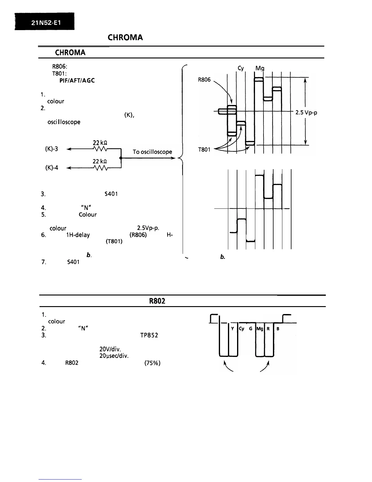
R806:
1 H-delay amp. control
. T801:
1 H-delay phase control
Note: PIFIAFTIAGC adjustments should have
been completed before starting this adjustment.
1.
Receive the “PAL COLOUR BAR” signal with
colour
bar generator.
2.
Connect the following resistance matrix to pins
3 and 4 of the connector (K), to which an
osci
I
loscope
is connected.
22
ka
(Q-4
Ahh
Resistance Matrix
3.
Set service switch
S401
at the Video Cut
position to cut-off the Y-signal.
4.
Turn on the “N” key the remote controller.
5.
Adjust the
Colour
control key of the remote
controller so that the output waveform of
colour
difference signal becomes Z.SVp-p.
6.
Adjust IH-delay amp. control
(R806)
and 1
H-
delay phase control (T801) so that the output
waveform shown in Fig. a is corrected to that
shown in Fig.
6.
7.
Return
5401
to CENTER position.
W Y
Cy
G
Mq
R B
Figure a. Waveform before the adjustment
-
c
Figure
b.
Waveform after the adjustment
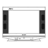
PAL SUB-COLOUR ADJUSTMENT:
R802
1.
Receive the “PAL COLOUR BAR” signal with
colour
bar generator.
2.
Turn on the
“N”
key on the remote controller.
3.
Connect oscilloscope to the
TP852
(red
cathode).
l
Voltage Range:
ZOV/div.
l
Sweep time: 20psec/div.
4.
Adjust
R802
so that the white signal (75%) and
red signal have the same level.
E
-
W
CY
G
W
T
Same level for the white and red outputs.
8