VIDEO CIRCUIT ADJUSTMENT
CRT CUT-OFF ADJUSTMENT
l
R853:
Red Bias control
l
R859:
Green Bias control
l
R865: Blue Bias control
l
Screen control (a part of
T602)
l
R857:
Green Drive control
l
R863: Blue Drive control
*
Note:
Prior to this adjustment, warm up the unit
with the beam current of more than 700uA for
more than
30
minutes.
1.
Receive “MONOSCOPE PATTERN” signal with
pattern generator.
6.
Turn
5401
(service switch) at the horizontal
line position.
2.
Set Red Bias control at
MIN
position.
Set Green Bias control at
MIN
position.
Set Blue Bias control at MIN position.
Set Green Drive control at CENTER position.
Set Blue Drive control at CENTER position.
3.
Turn the
“N”
key on the remote controller.
4.
Set the Screen control at MIN position.
5.
Connect the oscilloscope to
TP852
(red
cathode).
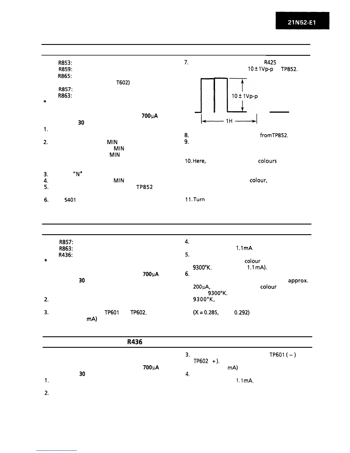
7.
Adjust Sub-Brightness control
R425
to obtain a
blanking pulse level of
10
+
lVp-p
at
TP852.
n
nqvpmp
I-1H-I
8.
Disconnect the oscilloscope
fromTP852.
9.
Slowly turn the Screen control clockwise until
the horizontal raster appears slightly, and
stop it.
11
.Turn
the Screen control counterclockwise until
the horizontal raster disappears, and stop it.
IO-Here,
one of the three
colours
(red, blue,
green) appears first as the Screen control is
turned. So, touching off the Bias control
belonging to the first
colour,
use and move
the other two controls so that the horizontal
raster becomes white.
WHITE BALANCE AND BACK GROUND
l
R857:
Green Drive control
l
R863: Blue Drive control
l
R436: Sub Contrast control
* Note:
Prior to this adjustment, warm up the unit
with the beam current of more than 700pA for
more than
30
minutes.
I. Receive “MONOSCOPE PATTERN” signal with
pattern generator..
2.
Set the Contrast control and Brightness
control at MAX position.
3.
Connect ammeter to TP601 and
TP602.
(Full scale: 3
mA)
4.
Adjust Sub-Contrast control so that the beam
current becomes
1.1
mA
(rough adjustment).
5.
Adjust Green Drive control and Blue Drive
control so that the
colour
temperature is at
9300°K.
(High beam:
1.1
mA).
6.
Adjust the Contrast control and Brightness
control so that the beam current is
approx.
200pA, and check that the colour temperature
is at 9300°K. If the temperature is not at
9300”K,
go back to “CRT CUT-OFF
ADJUSTMENT” and repeat the adjustment.
(X
=
0.285, Y = 0.292)
SUB-CONTRAST CONTROL: R436
* Note:
Prior to this adjustment, warm up the unit
with the beam current of more than 700uA for
more than
30
minutes.
1.
Receive “MONOSCOPE PATTERN” signal with
.
pattern generator..
3.
Connect beam ammeter to TP601
(-)
and
TP602 ( +).
(Full scale: 3
mA)
4.
Adjust Sub-Contrast control so that the beam
current becomes
1.1
mA.
2.
Set the Contrast and Brightness controls at
MAX position.
7