EasyManua.ls Logo

Sharp 25L-M100 User Manual

Sharp 25L-M100
50 pages
To Next Page IconTo Next Page
Page #1 background imageLoading...
Page #1 background image
1
25L-M100/180/S100/180
CL25M10,CL25S18
SERVICE MANUAL
COLOR TELEVISION
Chassis No. SN-91
In the interests of user-safety (Required by safety regulations in some countries) the set should be restored to its
original condition and only parts identical to those specified should be used.
S49F325L-M100
» ELECTRICAL SPECIFICATIONS........................................................................................................ 1
» IMPORTANT SERVICE SAFETY PRECAUTION ............................................................................... 2
» LOCATION OF USER'S CONTROL.................................................................................................... 6
» INSTALLATION AND SERVICE INSTRUCTIONS ............................................................................ 10
» CHASSIS LAYOUT ........................................................................................................................... 16
» BLOCK DIAGRAM ............................................................................................................................ 18
» SCHEMATIC DIAGRAMS ................................................................................................................. 20
» PRINTED WIRING BOARD ASSEMBLIES ....................................................................................... 38
» REPLACEMENT PARTS LIST .......................................................................................................... 41
» PACKING OF THE SET..................................................................................................................... 49
Page
25L-S100/180
CL25S18
25L-M100/180
CL25M10
SHARP CORPORATION
This document has been published to be used for after
sales service only.
The contents are subject to change without notice.
CONTENTS
25L-M100/180, 25L-S100/180
CL25M10, CL25S18
MODELS
ELECTRICAL SPECIFICATIONS
POWER INPUT ................................................... 120 V AC 60 Hz
POWER RATING
25L-M100/180, CL25M10 ................................................. 105 W
25L-S100/180, CL25S18 .................................................. 110 W
PICTURE SIZE ........................................... 2,032cm
2
(315sq inch)
CONVERGENCE............................................................. Magnetic
SWEEP DEFLECTION .....................................................Magnetic
FOCUS ............................................... Hi-Bi-Potential Electrostatic
INTERMEDIATE FREQUENCIES
Picture IF Carrier Frequency ..................................... 45.75 MHz
Sound IF Carrier Frequency ...................................... 41.25 MHz
Color Sub-Carrier Frequency..................................... 42.17 MHz
(Nominal)
AUDIO POWER
25L-M100/180, CL25M10 ............... 1.3W (at 10% distortion and
Dual CH Operate)
25L-S100/180, CL25S18 .... 1.3W +1.3W (at 10% distortion and
Dual CH Operate)
SPEAKER
SIZE ...................................................................... 8 cm (Round)
VOICE COIL IMPEDANCE ............................. 32 ohm at 400 Hz
ANTENNA INPUT IMPEDANCE
VHF/UHF .................................................... 75 ohm Unbalanced
TUNING RANGES
VHF-Channels .............................................................. 2 thru 13
UHF-Channels ............................................................ 14 thru 69
CATV Channels .......................................................... 1 thru 125
(EIA, Channel Plan U.S.A.)
Specifications are subject to change without
prior notice.
Question and Answer IconNeed help?

Do you have a question about the Sharp 25L-M100 and is the answer not in the manual?

Sharp 25L-M100 Specifications

General IconGeneral
BrandSharp
Model25L-M100
CategoryTV
LanguageEnglish

Summary

Electrical Specifications

Power Input

Details the power requirements for the television set.

Power Rating

Specifies power consumption for different models.

Picture Size

Indicates the diagonal screen measurement in cm and sq inches.

Audio Power

Details audio output power and distortion levels.

Important Service Safety Precaution

Warning

Lists essential safety warnings for servicing the television.

X-Radiation and High Voltage Limits

Outlines precautions and limits for X-radiation and high voltage.

Before Returning the Receiver (Fire & Shock Hazard)

Safety Notice

Emphasizes using identical replacement parts for safety.

Location of User's Control

Front Panel Controls

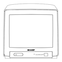
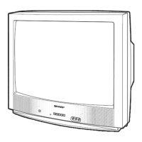
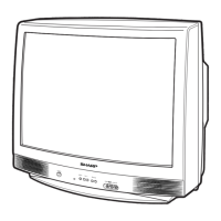
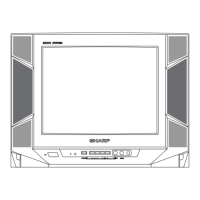
Identifies controls located on the front panel of the TV.

Basic Remote Control Functions

Explains the functions of buttons on the remote control.

Installation and Service Instructions

Circuit Protection

Describes the fuse protecting the receiver circuit.

X-Radiation Protector Circuit Test

Details the procedure to test the X-radiation protection circuit.

High Voltage Check

Explains how to check and verify the high voltage level.

Service Adjustment

VCO Adjustment

Procedure for adjusting the Voltage Controlled Oscillator.

RF AGC Adjustment

Steps for adjusting the Radio Frequency Automatic Gain Control.

Screen Adjustment

Guide for adjusting the picture screen settings.

White Balance Adjustment

Steps to adjust the white balance for accurate colors.

Sub-Picture Adjustment

Procedure for adjusting sub-picture settings like contrast.

Sub-Tint Adjustment

Steps to adjust the tint for natural flesh tones.

Sub-Color Adjustment

Guide for adjusting the color level for optimal display.

Sub-Brightness Adjustment

Procedure for adjusting the brightness level.

Vertical-Size Adjustments

Steps to adjust the vertical size of the picture.

Vertical Phase Adjustment

Procedure for adjusting the vertical phase.

Horizontal Position Adjustment

Steps to adjust the horizontal position of the picture.

Caption Position Adjustment (Horizontal)

Guide for positioning closed caption text horizontally.

3.58MHz Trap Adjustment

Procedure to adjust the 3.58MHz trap for normal viewing.

Sharpness and Audio Balance Adjustments

Steps for adjusting sharpness and audio balance.

Energy Save Offset Adjustment

Procedure for presetting the energy save function.

Other Adjustments

Lists additional minor adjustments like DDE OFFSET and OSD SETUP.

MTS Adjustment

MTS Level Adjustment

Procedure for adjusting the MTS level for stereo sound.

MTS VCO Adjustment

Steps to adjust the MTS Voltage Controlled Oscillator.

Filter Adjustment

Procedure for adjusting the stereo pilot signal filter.

Separation Adjustment

Steps to adjust the stereo channel separation.

Chassis Layout

PWB-A: MAIN Unit

Shows the component layout for the main circuit board (PWB-A).

PWB-B: CRT Unit

Illustrates the component layout for the CRT circuit board (PWB-B).

PWB-H: FRONT AV Unit

Shows the component layout for the front AV circuit board (PWB-H).

Block Diagram

PWB-A: MAIN Unit

Illustrates the functional blocks and connections of the main unit.

PWB-H: FRONT AV Unit

Shows the functional blocks and connections of the front AV unit.

PWB-B: CRT Unit

Illustrates the functional blocks and connections of the CRT unit.

Description of Schematic Diagram

Notes

Provides general notes and definitions for understanding schematic symbols.

Voltage Measurement Conditions

Specifies conditions for measuring DC voltages in the circuit.

Waveform Measurement Conditions

Outlines conditions for capturing waveform measurements.

Schematic Diagram

CRT and Front AV Unit

Details the schematic for the CRT and Front AV units.

Printed Wiring Board Assemblies

PWB-A: MAIN Unit (Wiring Side)

Shows the component layout on the wiring side of the main unit PCB.

PWB-A: MAIN Unit (Chip Parts Side)

Displays the component layout on the chip parts side of the main unit PCB.

PWB-B: CRT Unit (Wiring Side)

Shows the component layout on the wiring side of the CRT unit PCB.

PWB-H: FRONT AV Unit (Wiring Side)

Displays the component layout on the wiring side of the front AV unit PCB.

Parts List

Parts Replacement

Emphasizes safety when replacing parts and using identical components.

How to Order Replacement Parts

Provides instructions on how to order replacement parts correctly.

Packing of the Set

Packing Diagram

Illustrates the components and their placement within the packing case.

Related product manuals