7
Part names
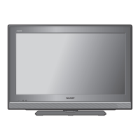
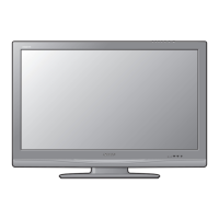
TV (Front)
POWER indicator
Light off Power off
Lighted (Red) The TV is in standby mode.
Lighted (Green) The TV is on.
Remote control sensor
OPC sensor
TV (Rear)
9
8
7
6
10
12
13
11
14
15
1
2
3
4
5
18
16
17
1 POWER (On/Off) button
2 MENU button
3 INPUT button
4 Channel up (
r
)/down (
s
) buttons
5 Volume up (
e
)/down (
f
) buttons
6 DIGITAL AUDIO OUTPUT terminal
7 INPUT 7 (PC) terminals*
8 RS-232C terminal
9 Antenna input terminal
10 INPUT 4 terminals
11 INPUT 5 terminals
12 INPUT 6 terminals
13 AUDIO OUT terminal
14 INPUT 2 (HDMI) terminal
15 INPUT 1 (HDMI) terminal*
16 USB terminal**
17 INPUT 3 (HDMI) terminal
18 Headphone jack
* The INPUT 1 and INPUT 7 terminals can both use the same analogue audio input terminal. However, the proper item
must be selected in the “PC audio select” menu. (See page 15.)
** USB terminal use for USB Media Player. (See page 25.)
• The illustrations in this operation manual are for explanation purposes and may vary slightly from the actual operations.
Regarding the headphone jack
• Use headphones with a stereo mini plug ( 3.5 mm).
• Be sure to unplug headphones from the jack when they are not
in use.
• The speakers do not output volume when headphones are
plugged in.
• The “Audio” menu cannot be operated when headphones are
plugged in.
Volume display when headphones are plugged in
20
LC32M400X_EN_CS2_A5.indd 7LC32M400X_EN_CS2_A5.indd 7 6/9/2011 2:35:04 PM6/9/2011 2:35:04 PM

 Loading...