Do you have a question about the Sharp AR-M258 and is the answer not in the manual?
| Brand | Sharp |
|---|---|
| Model | AR-M258 |
| Category | All in One Printer |
| Language | English |
Important safety warnings and precautions to follow during machine servicing to prevent electrical shock or fire.
General safety measures, handling guidelines, and precautions for high-voltage areas during servicing.
Advises on suitable locations for machine installation to ensure proper function and avoid damage.
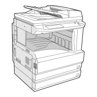
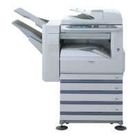
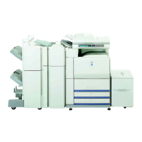
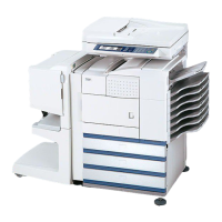
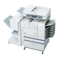
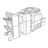
Overview of the product lineup and available optional components for the system.
Table detailing compatible combinations of main units and optional equipment.
Details machine type, external dimensions, weight, and power supply specifications.
Specifies operational parameters for common tasks and copy mode features.
Engine specifications covering various sections like paper feed, scanning, and fusing.
Outlines additional, copy, and expanded functional features of the system.
Details safety standards compliance and environmental protection measures, including ozone levels.
Specifies installation space, ambient conditions, and IMC board functions.
Details the SPLC printer function, driver specifications, and print quality settings.
Specifies paper handling capabilities, including feed direction and print areas.
Describes the machine's center reference system for formatting and center distribution.
Details the basic printer functions specific to the AR-M258/M318 models.
Provides a table of consumable parts like toner cartridges and developer, categorized by region.
Lists essential maintenance parts and their availability for different model series.
Provides instructions for installing the machine, covering environmental factors and power source.
Instructions for removing protective materials, fixing screws, and pins before initial use.
Step-by-step guides for installing the developer and toner cartridges.
Guides on adjusting toner density sensor and setting paper type/size for trays.
Provides instructions for installing optional hardware components.
Instructions for mounting additional memory and installing expansion kits like AR-PK1N.
Details installation of the MX-NSX1 network scanner kit and AR-PF1/PF2 barcode kits.
Instructions for installing AR-SM5/SM6 memory expansion boards.
Identifies and describes the function of external components and sections of the machine.
Details the internal structure of the machine, identifying key components and their functions.
Explains the functions of each key and indicator on the machine's operation panel.
Details the job status screen, allowing users to monitor and manage ongoing or stored jobs.
Identifies and lists motors, solenoids, clutches, and sensors used in the machine's operation.
Identifies the various Printed Wiring Board (PWB) units within the machine.
Describes different sections of the machine and the function of their key components.
Provides a comprehensive list of adjustable items categorized by machine section.
Details the procedures for adjusting copier functions to ensure optimal performance.
Details procedures for adjusting developing bias and grid bias voltages for copy modes.
Covers adjustments for mechanism section, including print start and RSPF lead edge positions.
Guides on adjusting paper off-center, left edge void, and rear edge void for proper handling.
Details adjustments for scanning direction distortion and magnification ratios.
Details how to adjust image density and exposure levels for optimal print output.
Outlines the purpose and functions of the simulation mode for diagnostics and adjustments.
Details operating procedures for code-type simulations, including entering codes and navigating menus.
Guides on how to modify adjustment values using the touch panel interface during simulation.
Provides a list of simulation codes targeted for specific adjustments and checks.
A comprehensive list of simulation codes, their functions, and associated sub-codes.
Details specific simulation procedures for scanner, RSPF, and finisher operations.
A maintenance table indicating parts check, cleaning, replacement, or lubrication intervals.
Provides detailed steps for disassembling and assembling key machine units.
Details the disassembly and assembly of the process unit, including drum and main charger.
Details the disassembly and assembly of the fusing section components.
Details the disassembly and assembly of the optical section components.
Details the disassembly and assembly of the paper feed section components.
Details disassembly of the side door unit components.
Details disassembly of the drive section components.
Details disassembly of the operation section components.
Details the procedure for updating the Flash ROM firmware on various PWBs.
Outlines the method for downloading copier, fax, and printer firmware to the machine.
Provides troubleshooting steps for errors that may occur during the download process.
Lists available key operator programs and their default settings for copier functions.
Details setting programs for printer and network scanner functions.
Explains E-mail status transmission and alert messages based on machine events.
Provides a high-level block diagram of the machine's electrical system and component connections.
Presents detailed wiring diagrams illustrating the electrical connections between components.
Illustrates wiring connections between MCU PWB and other units like Operation Panel, Optical Base Plate, and OP Connector.
Illustrates wiring connections between MCU PWB and paper exit units, and drive components.
Illustrates wiring connections between MCU PWB, Option Cassette, and Power Supply PWB.
Illustrates wiring connections between MCU PWB, Manual Feed Unit, and Main Unit Cassette.
Illustrates board-to-board connections between various PWBs.
Provides notes on using lead-free solder thread and its properties compared to conventional solder.
Offers guidance on proper soldering techniques for lead-free solder to prevent damage.
Provides safety cautions regarding battery replacement and proper disposal procedures.