AY-XPC15PU
3 – 6
Indoor and
outdoor
units oper-
ate.
Normal
blinking
or OFF
{{{{{Timer (Orange) 26 1 Indoor unit
room tem-
perature
thermistor
Indoor unit room
temperature
thermistor
(1) Check connector of
thermistor for
secure installation.
(1) Replace the ther-
mistor.
{{ { Operation (Green)
{ Plasmacluster(Blue)
Operation (Green)
Plasmacluster(Blue)
Operation (Green)
Plasmacluster(Blue)
(2) Check the tempera-
ture properties of
the thermistor.
(2) Replace the ther-
mistor.
{{{{{Timer (Orange) 2 Indoor unit
pipe tem-
perature
thermistor
Indoor unit pipe
temperature
thermistor
(1) Check connector of
thermistor for
secure installation.
(1) Replace the ther-
mistor.
{{ {
{
(2) Check the tempera-
ture properties of
the thermistor.
(2) Replace the ther-
mistor.
{{{{{Timer (Orange) 3 Indoor unit
valve tem-
perature
thermistor
Indoor unit valve
temperature
thermistor
(1) Check connector of
thermistor for
secure installation.
(1) Replace the ther-
mistor.
{{ {
{{
(2) Check the tempera-
ture properties of
the thermistor.
(
2) Replace the ther-
mistor.
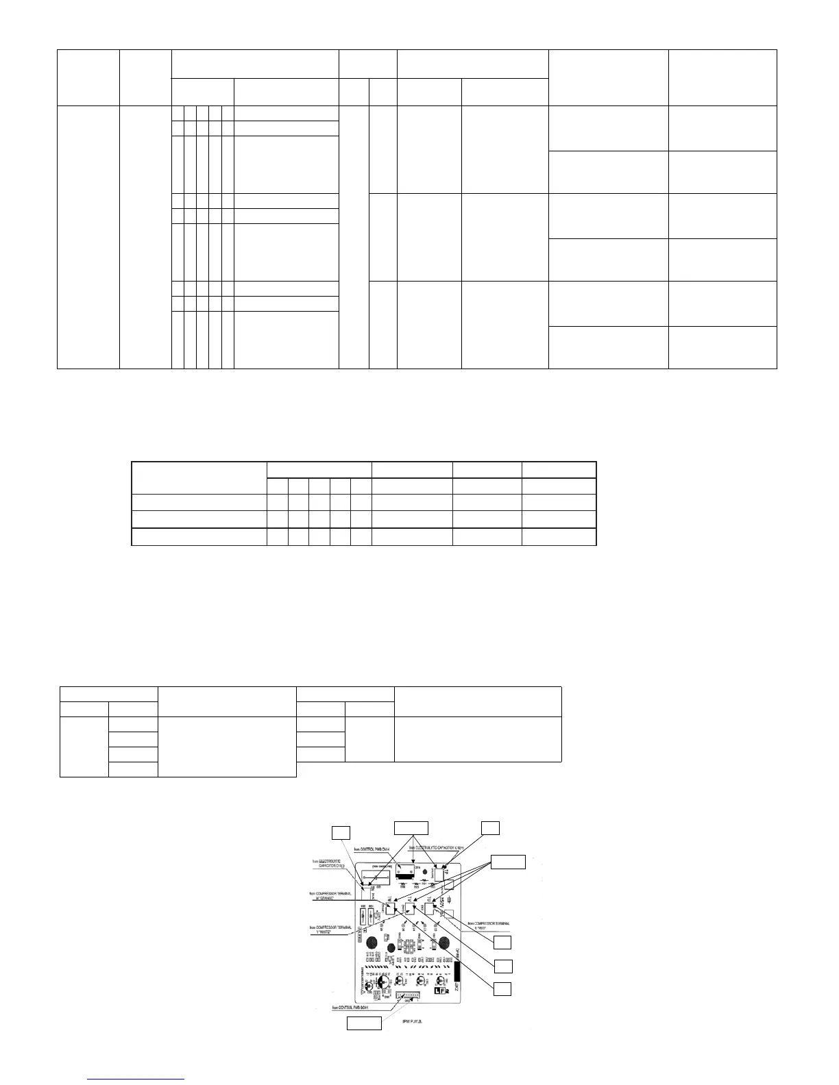
Problem
symptom
Outdoor
unit indi-
cation
(LED1)
Indoor unit Malfunc-
tion No.
Content of diagnosis Check point Action
Lamp Main Sub Main Sub
o
*Remark
The malfunction No. is calculated using the following way.
Example)
Indoor unit lamp
o
Lamp Calculation Main Sub
168421
Timer (orange) OOOOO
Operation (Green) O O 4+1=5 5
Plasmacluster (blue) O 2 2
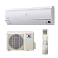
IPM CHECK METHOD
1. Turn off the power.
2. Make sure that the electrolytic capacitor voltage is approx. 0 V.
3. Remove all connectors of the IPM PWB.
4. Measure the resistance between terminals using a tester.
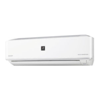
Measuring points of terminals are shown in the figure below.
Analog tester
Normal Resistance
Analog tester
Normal Resistance
--+-
TP
TN
∞
*(Few MΩ)
TU
TN
∞
(Few MΩ)
VTUT
WTVT
retset latigiD yb :eulav ) (* WT
IPM printed wiring board
REMOVE
REMOVE
TN
TP
TU
TV
TW
REMOVE