BD-HP90S
2 – 1
BDHP90S
Service Manual
CHAPTER 2. OPERATION MANUAL
[1] PARTS NAMES
NOTE
When you insert or remove a USB memory
device, be sure to turn the main power off.
*
NOTE
Some optical and/or HDMI cables may not fit in the compartment.•
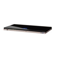
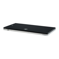
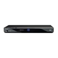
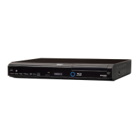
Main Unit (Front)
Major Components
1
5
8910
6 7
2 3
4
POWER (On/Standby) indicator
AQUOS PURE MODE indicator
3D indicator
5
6
7
USB terminal
POWER (Power)
Remote control sensor “Front”
8
9
10
Remote control sensor “Top”
BD/DVD/CD mode indicator
Disc slot
EJECT
1
2
3
4
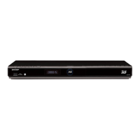
Main Unit (Rear)
1
3
4
5 6 7 8
2
9
DC IN terminal (p. 25)
OPTICAL DIGITAL AUDIO OUT terminal
HDMI OUT terminal
ETHERNET terminal
Screw holes for VESA 75 Mount
Screw size: M4 (Maximum length = Mount plate thickness + 6 mm)
Recommended tightening torque for M4 screws: 1.2±0.1N·m (12.2±1kgf·cm)
5
6
7
8
9
Cooling fan
The cooling fan operates while the
power to the Player is on.
Terminal cover
Selector switch for Remote control
sensor
Screw hole for installing the vertical
stand
1
2
3
4
Model label