CD-C612
– 34 –
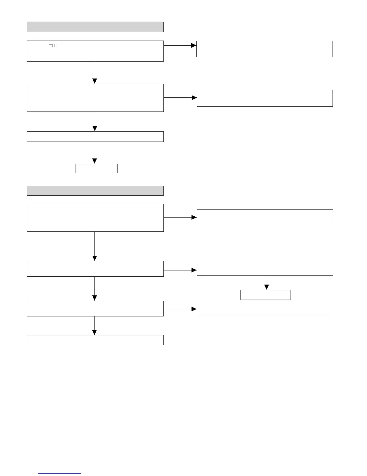
• When the turntable fails to stop.
Is from 5 V till 2.5V down pulse (approx. 300 ms)
Check the SWM3 and the wiring from the IC701 pin 21 to the
SWM3.
No
No
input into the IC701 pin 21 when the turntable is rotating?
5V
2.5V
0V
Yes
Check IC2 pin26 Q91 and Q93 and the periphery.
Check the MECHA UP SW and the wiring from the IC701 pin
21 to the MECHA UP SW.
No
Yes
Is there following voltage input on the IC701 pin 21 in the
specific state?
When the CD mechanism is moved up: 0V
In other states: 4.3V
Yes
Is there following voltage input on the IC701 pin 21 in the
specific state?
In other states: 4.3V
When the CD mechanism is moved up: 0V
• When turntable fails to move.
Check the MECHA UP SW and the wiring from the IC701 pin
21 to the MECHA UP SW.
Is 4V output from the Q91 emitter during operation stated
above?
Yes
Yes
Check the wiring of IC2 pin 26 and Q93 pin 2.
OK
No
No
Is L output from the IC2 pin 26 during SEC when the disc skip
switch is pressed?
Yes
Check turntable motor and turntable mechanism.
Check Q91, Q93 and the periphery.
IC701 defective.
IC2 defective.