– 17 –
CD-DD4500
fL: Low-range frequency
fH: High-range frequency
• AM adjustment and confirmation
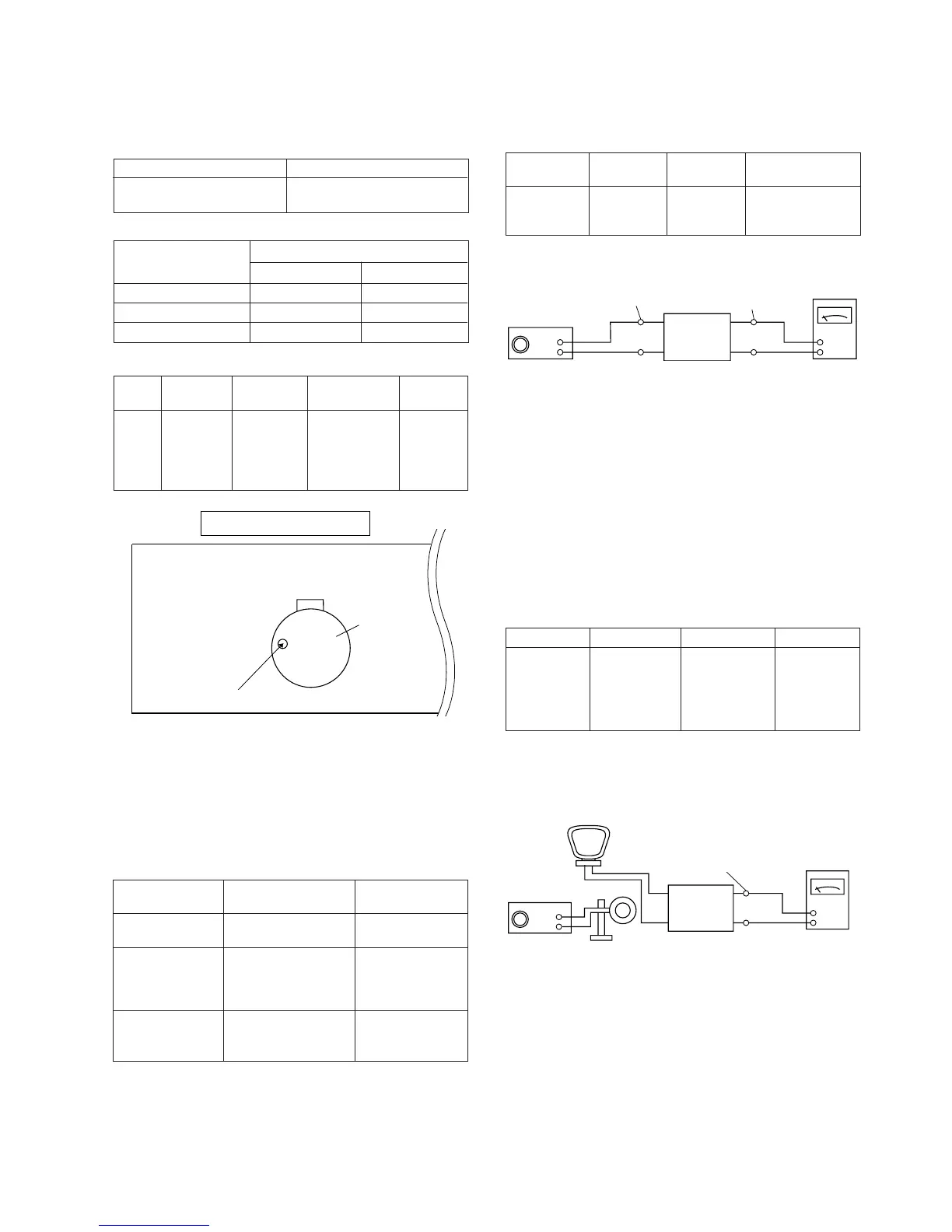
Figure 17-3 AM IF
TUNER SECTION
• Setting the Test Mode
While holding down the MEMORY/SET button and the X-
BASS button, press the POWER button. Frequencies are
rewritten in memory as shown in table 17. Call them using the
VOLUMN knob of tuner circuit adjustment and check.
Note that once you reinitialize the settings, the frequencies
recorded by users will be changed.
Preset No. Frequency
P01 87.5 MHz P06 530 kHz
P02 108.0 MHz P07 1,720 kHz
P03 90.0 MHz P08 600 kHz
P04 106.0 MHz P09 1,400 kHz
P05 98.0 MHz P10 990 kHz
Adjusting item
Adjusting object
Adjusting
method
IF Adjust the indication of Set IF wafeform
T351 set to 1,720 kHz.
450 kHz to maximum.
Frequency cover fL: T306 (530 kHz) fL: 1.3 ± 0.1 V
(VT line voltage of Adjust the indication fH: 8.5 ± 1.3 V
TP301) of set to 530 kHz. (Only confirmation)
fH: (1,720 kHz)
Tracking fL: T302 (990 kHz) Set the output of
speaker terminal
to maximum.
AM signal oscillator Frequency 400 Hz, 30 %, AM modulation
• FM mute level adjustment
Frequency
Adjusting
object
Adjusting
method
98.0 MHz 26 dB(EMF) VR351 Input: CNP301
Output: Speaker
Terminal
FM signal oscillator Frequency 1 kHz, 22.5 kHz
Adjusting object
Preset No.
Frequency
Figure 17-2 FM Mute Level
Table 17
Electronic
Voltmeter
GND
AM Loop Antenna
AM signal oscillator
Loop Antenna
UNIT
IF : Speaker Terminal
Frequency cover: TP301
Electronic
Voltmeter
UNIT
FM signal oscillator
CNP301
Speaker
Terminal
• Erasing the registered broadcast station
When the power is off, press and hold the TUNER (BAND)
button and the X-BASS button, and then press the POWER
button.
All the registered stations are erased.
ADJUSTMENT
MECHANISM SECTION
• Driving Force Check
Torque Meter Specified Value
Play: TW-2111 Tape 1: Over 80 g
Tape 2: Over 80 g
• Torque Check
Torque Meter
Tape 2
Play: TW-2111 30 to 80 g.cm 30 to 80 g.cm
Fast forward: TW-2231 — 70 to 180 g.cm
Rewind: TW-2231 — 70 to 180 g.cm
Specified Value
Tape 1
Specified
Value
Adjusting
Point
Instrument
Connection
Test Tape
Normal MTT-111 Variable 3,000 ± 30 Hz Speaker
speed Resistor in Terminal
motor. (Load
resistance:
6 ohms)
• Tape Speed
Figure 17-1
TAPE MECHANISM
Tape
Motor
Variable Resistor in motor