CD-DP2500W/DK2500W
– 12 –
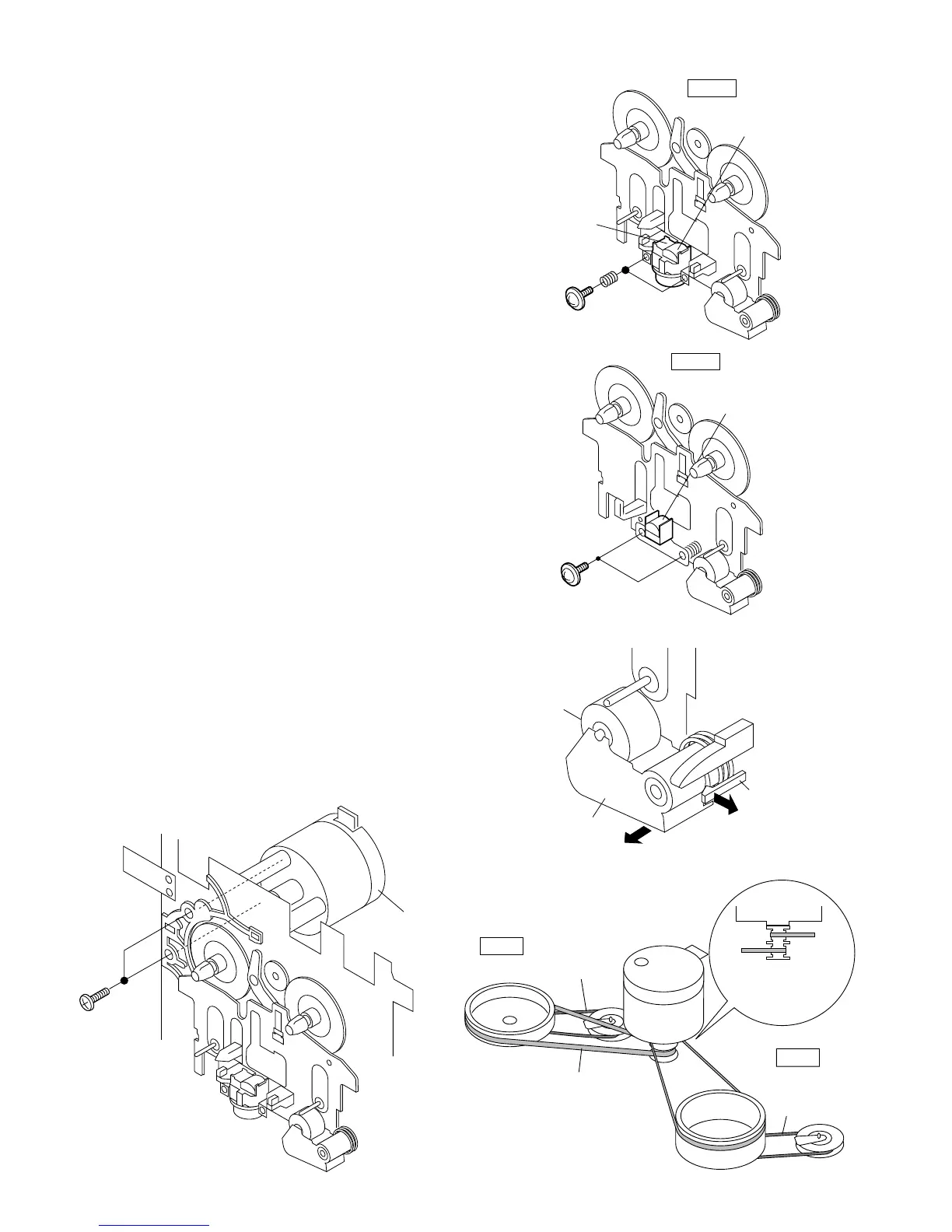
REMOVING AND REINSTALLING THE MAIN PARTS
TAPE MECHANISM SECTION
Perform steps 1 to 7 and 10 of the disassembly method to
remove the tape mechanism.
How to remove the record/playback and erase
heads (TAPE 2) (See Fig. 12-1)
1. When you remove the screw (A1) x 2 pcs., the recording/
playback head and three-dimensional head of the erasing
head can be removesd.
How to remove the playback head (TAPE 1)
(See Fig. 12-2)
1. When you remove the screw (B1) x 2 pcs., the playback
head.
How to remove the pinch roller (TAPE 1/2)
(See Fig. 12-3)
1. Carefully push the inside claw to remove it. The pinch roller
pawl in the direction of the arrow <A>, and remove the pinch
roller (C1) x 1 pc., in the direction of the arrow <B>.
Note:
When installing the pinch roller, pay attention to the spring
mounting position.
How to remove the belt (TAPE 1) (See Fig. 12-4)
1. Remove the main belt (D1) x 1 pc., from the motor side.
2. Remove the FF/REW belt (D2) x 1 pc.
How to remove the belt (TAPE 2) (See Fig. 12-4)
1. Remove the main belt (E1) x 1 pc., from the motor side.
2. Remove the FF/REW belt (E2) x 1 pc.
How to remove the motor (See Fig. 12-5)
1. Remove the screws (F1) x 2 pcs., to remove the motor.
Figure 12-1
Figure 12-2
Figure 12-3
Figure 12-4Figure 12-5
TAPE2
TAPE1
Main Belt
(D1)x1
TAPE2
Main Belt
(E1)x1
TAPE1
Main Belt
FF/REW
Belt
(E2)x1
FF/REW
Belt
(D2)x1
Motor
Motor
(B1)x2
Ø2 x 9mm
TAPE 1
Playback
Head
Pinch Roller
(C1)x1
Pinch Roller
Pawl
<A>
<B>
(A1)x2
Ø2 x 5mm
TAPE 2
Record/Playback
Head
Erase Head
(F1) x2
Ø 2.6 x 5mm
Motor