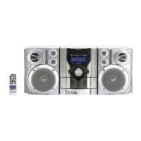
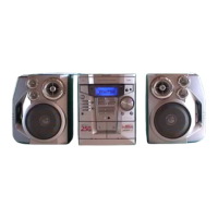
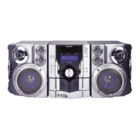
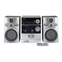
CD-E99
– 2 –
SPECIFICATIONS
FOR A COMPLETE DESCRIPTION OF THE OPERATION OF THIS UNIT, PLEASE REFER
TO THE OPERATION MANUAL.
General
Amplifier
Power source AC 120 V, 60 Hz
Power
consumption
165 W
Dimensions Width: 10-5/8" (270 mm)
Height: 13" (330 mm)
Depth: 13-15/16" (355 mm)
Weight 19.6 lbs. (8.9 kg)
Output power 180 watts minimum RMS per channel into 6
ohms from 60 Hz to 20 kHz, 10% total har-
monic distortion
Output terminals Speakers: 6 ohms
Headphones: 16 - 50 ohms (recommended:
32 ohms)
Input terminals Video/Auxiliary (audio signal): 500 mV/47 k
ohms
CD player
Tuner
Cassette deck
Type 3-disc multi-play compact disc player
Signal readout Non-contact, 3-beam semiconductor laser
pickup
D/A converter 1-bit D/A converter
Frequency
response
20 - 20,000 Hz
Dynamic range 90 dB (1 kHz)
Frequency range FM: 87.5 - 108 MHz
AM: 530 - 1,720 kHz
Frequency
response
50 - 14,000 Hz (normal tape)
Signal/noise ratio 55 dB (TAPE 1, playback)
50 dB (TAPE 2, recording/playback)
Wow and flutter 0.3 % (WRMS)
Type 3-way 4-speaker system with passive radia-
tor
Super tweeter 2
2" (5 cm) tweeter
6-1/2" (16 cm) woofer
6-1/2" (16 cm) passive radiator
Maximum input
power
360 W
Rated input power 180 W
Impedance 6 ohms
Dimensions Width: 10-7/8" (277 mm)
Height: 13" (330 mm)
Depth: 10-3/4" (273 mm)
Weight 11.2 lbs. (5.1 kg)/each
CD-E99
CP-E99
IMPORTANT SERVICE NOTES
BEFORE RETURNING THE AUDIO PRODUCT
(Fire & Shock Hazard)
Before returning the audio product to the user, perform the
following safety checks.
1. Inspect all lead dress to make certain that leads are not
pinched or that hardware is not lodged between the chassis
and other metal parts in the audio product.
2. Inspect all protective devices such as insulating materials,
cabinet, terminal board, adjustment and compartment covers
or shields, mechanical insulators etc.
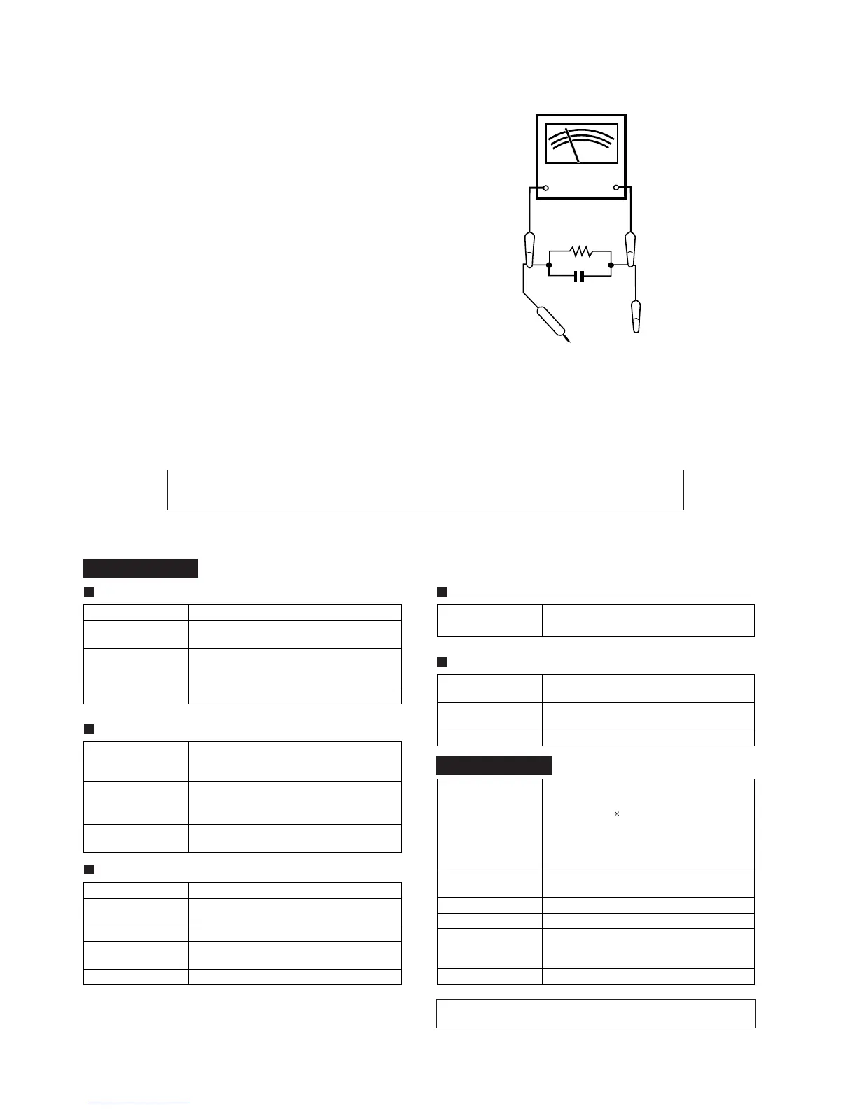
3. To be sure that no shock hazard exists, check for leakage
current in the following manner.
* Plug the AC line cord directly into a 120 volt AC outlet.
* Using two clip leads, connect a 1.5 kohm, 10 watt resistor
paralleled by a 0.15 µF capacitor in series with all exposed
metal cabinet parts and a known earth ground, such as
conduit or electrical ground connected to earth ground.
* Use a VTVM or VOM with 1000 ohm per volt, or higher,
sensitivity to measure the AC voltage drop across the
resistor (See diagram).
* Connect the resistor connection to all exposed metal parts
having a return path to the chassis (antenna, metal cabinet,
screw heads, knobs and control shafts, escutcheon, etc.)
and measure the AC voltage drop across the resistor.
All check must be repeated with the AC line cord plug connection
reversed.
Any reading of 0.3 volt RMS (this corresponds to 0.2 milliamp.
AC.) or more is excessive and indicates a potential shock
hazard which must be corrected before returning the audio
product to the owner.
TO EXPOSED
METAL PARTS
CONNECT TO
KNOWN EARTH
GROUND
TEST PROBE
0.15 µF
1.5 kohms
10 W
VTVM
AC SCALE
Specifications for this model are subject to change without prior
notice