EasyManua.ls Logo

Sharp CD-G10000 User Manual

Sharp CD-G10000
140 pages
To Next Page IconTo Next Page
Page #1 background imageLoading...
Page #1 background image
CD-G10000/CP-G10000S
SERVICE MANUAL
In the interests of user-safety the set should be restored to its
original condition and only parts identical to those specified be
used.
No. S1506CDG10000
SHARP CORPORATION
CONTENTS
Parts marked with " " are important for maintaining the safety of the set. Be sure to replace these parts with specified ones for
maintaining the safety and performance of the set.
This document has been published to be used
for after sales service only.
The contents are subject to change without notice.
CHAPTER 1. GENERAL DESCRIPTION
[1] Specifications ................................................. 1-1
[2] Names of parts............................................... 1-2
CHAPTER 2. ADJUSTMENTS
[1] Mechanism section ........................................ 2-1
[2] Tuner section ................................................. 2-1
[3] TEST MODE .................................................. 2-2
[4] CD SECTION ................................................. 2-4
[5] CD section...................................................... 2-4
[6] Standard Specification of Stereo System
Error Message Display Contents ................... 2-4
[7] CD Changer mechanism section ................... 2-5
CHAPTER 3. MECHANISM BLOCKS
[1] Caution on disassembly ................................. 3-1
[2] Removing and reinstalling the main parts ........ 3-5
CHAPTER 4. DIAGRAMS
[1] Block diagrams............................................... 4-1
CHAPTER 5. CIRCUIT DESCRIPTION
[1] Notes on schematic diagram .........................5-1
[2] Types of transistor and LED ..........................5-1
[3] Waveforms of CD circuit ................................5-2
[4] Voltage...........................................................5-3
CHAPTER 6. CIRCUIT SCHEMATICS AND PARTS
LAYOUT
[1] Schematic diagram........................................6-1
[2] Wiring side of PWB......................................6-13
CHAPTER 7. FLOWCHART
[1] Troubleshooting.............................................7-1
CHAPTER 8. OTHERS
[1] Function table of IC .......................................8-1
[2] FL Display....................................................8-10
Parts Guide (CD-G10000)
Parts Guide (CP-G10000S)
MINI COMPONENTSYSTEM
CD-G10000
MODEL
CD-G10000 Mini Component System consisting of CD-G10000
(main unit) and GBOXSA090AWM1 (rear speaker system).
SPEAKER SYSTEM
CP-G10000S
CP-G10000S Speaker System consisting of CP-G10000S
(front
speaker system) and CP-SW10000S (active subwoofer).
MODEL
jomi

Questions and Answers:

Sharp CD-G10000 Specifications

General IconGeneral
CD PlayerYes
Radio TunerYes
BluetoothNo
USB PortNo
Speaker Configuration2.0
Playable MediaCD
Tuner BandsFM, AM
Speakers2 speakers included

Summary

Important Service Notes

Pre-Return Safety Checks

Details safety checks to perform before returning the audio product to the user, including fire and shock hazard prevention.

Chapter 1: General Description

Specifications Overview

Provides detailed technical specifications for the CD-G10000 and CP-G10000S models, including power, dimensions, and output.

Part Identification

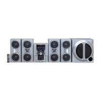
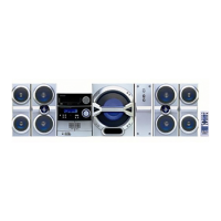
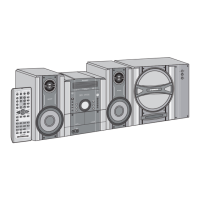
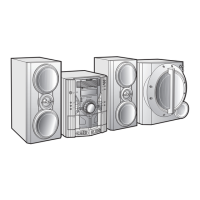
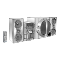
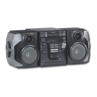
Identifies and labels various parts of the CD-G10000 unit on the front, display, and rear panels.

Chapter 2: Adjustments

Mechanism Section Adjustments

Details the procedures for adjusting the tape mechanism, including torque and speed checks.

Tuner Section Adjustments

Outlines the steps for adjusting the AM and FM RF/IF stages, including frequency and signal generator settings.

Test Mode Procedures

Explains how to enter and operate the unit's test mode for diagnostics and adjustments.

CD Section Adjustment Items

Lists items adjusted automatically within the CD system, such as offset, tracking balance, and gain.

CD Error Codes

Describes CD error codes, their explanations, and how 'CHECKING' is displayed.

Error Message Display Specifications

Details standard error message display contents for CD changer mechanism, DSP communication, and tuner PLL.

CD Changer Mechanism Details

Illustrates specific parts of the CD changer mechanism, including half gears and their arrangement.

Chapter 3: Mechanism Blocks

Disassembly Precautions

Provides essential safety notes and procedures to follow when disassembling and reassembling the unit.

Main Part Removal and Reinstallation

Details procedures for removing and reinstalling main components like tape heads, belts, and motors.

Tape Mechanism Section

Outlines steps for removing the tape mechanism, including heads, belts, and motor.

CD Mechanism Section Removal

Describes the steps to remove the CD mechanism, pickup unit, gears, and shaft.

Changer Mechanism Section: CD Disc Removal

Explains how to remove the CD disc tray and CD mechanism to access the disc.

Tray/Cam/Changer Motor PWB Removal

Details the removal of tray motor, main cam motor, and 5-changer motor PWB.

Chapter 4: Diagrams

Block Diagrams Overview

Presents block diagrams illustrating the system's functional interconnections for CD-G10000.

Chapter 5: Circuit Description

Schematic Diagram Notes

Explains symbols for resistors, capacitors, and conventions used in schematic diagrams.

Transistor and LED Types

Lists common transistor and LED types used in the circuit, referencing their part numbers.

CD Circuit Waveforms

Displays various waveforms from the CD circuit, indicating signal behavior at specific IC pins.

Voltage Measurements

Provides a table of voltage measurements at various IC pins for both CD-G10000 and CP-G10000S units.

Chapter 6: Circuit Schematics and Parts Layout

Schematic Diagram (CD-G10000)

Presents the schematic diagram for the CD-G10000 unit, detailing circuit connections.

PWB Wiring Side Diagrams

Illustrates the wiring side of various Printed Wiring Boards (PWBs) for component placement and routing.

Chapter 7: Flowchart

Troubleshooting Guide

Provides a structured troubleshooting guide for common CD playback issues, including cleaning and error codes.

Chapter 8: Others

IC Function Tables

Details the function table for CD Servo IC1 (LC78648E), listing pin names, I/O, and reset settings.

FL Display Pinout and Grid Assignment

Describes the FL display's pin connections and grid assignments for displaying information.