EasyManua.ls Logo

Sharp CD-K7000V User Manual

Sharp CD-K7000V
80 pages
To Next Page IconTo Next Page
Page #1 background imageLoading...
Page #1 background image
– 1 –
CD-K7000V,CP-C7000
No. S6051CDK7000V
CONTENTS
Page
SAFETY PRECAUTION FOR SERVICE MANUAL ........................................................................................................... 2
VOLTAGE SELECTION ..................................................................................................................................................... 2
SPECIFICATIONS ............................................................................................................................................................. 3
NAMES OF PARTS ........................................................................................................................................................... 4
OPERATION MANUAL ...................................................................................................................................................... 7
DISASSEMBLY.................................................................................................................................................................. 9
REMOVING AND REINSTALLING THE MAIN PARTS ................................................................................................... 12
ADJUSTMENT ................................................................................................................................................................. 14
NOTES ON SCHEMATIC DIAGRAM .............................................................................................................................. 16
BLOCK DIAGRAM ........................................................................................................................................................... 17
SCHEMATIC DIAGRAM / WIRING SIDE OF P.W.BOARD............................................................................................. 21
VOLTAGE ........................................................................................................................................................................ 43
WAVEFORMS OF CD CIRCUIT...................................................................................................................................... 44
TROUBLESHOOTING ..................................................................................................................................................... 45
FUNCTION TABLE OF IC................................................................................................................................................ 49
FL DISPLAY ..................................................................................................................................................................... 64
REPLACEMENT PARTS LIST/EXPLODED VIEW
In the interests of user-safety the set should be restored to its
original condition and only parts identical to those specified be
used.
SERVICE MANUAL
This document has been published to be used
for after sales service only.
The contents are subject to change without notice.
SHARP CORPORATION
NTSC/PAL
CD-K7000V
MODEL
VIDEO CD MINI SYSTEM
CP-C7000
MODEL
SPEAKER SYSTEM
Question and Answer IconNeed help?

Do you have a question about the Sharp CD-K7000V and is the answer not in the manual?

Sharp CD-K7000V Specifications

General IconGeneral
BrandSharp
ModelCD-K7000V
CategoryCD Player
LanguageEnglish

Summary

Safety Precautions

Voltage Selection

Procedure for selecting the correct AC voltage for operation.

Specifications

System and Component Specifications

General, Video CD, Tuner, Cassette Deck, and Speaker system specifications.

Names of Parts

CD-K7000V Front Panel Parts

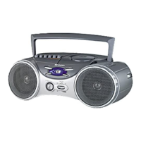
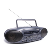
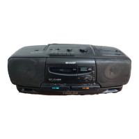
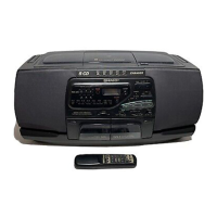
Identification of parts on the front panel of the CD-K7000V.

Display and Rear Panel Parts

Identification of display indicators and rear panel components.

Remote Control and Speaker Parts

Main and Sub Speaker Parts

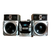
Components and assembly of the main and sub speaker units.

Preparation for Use

AC Power Connection and Clock Setting

Steps for AC power connection, voltage selection, and clock setting.

Microcomputer Reset and Remote Use

Disassembly Procedures

CD-K7000V Unit Disassembly

Step-by-step instructions for disassembling the CD-K7000V unit.

CP-C7000 Speaker Disassembly

Step-by-step instructions for disassembling the CP-C7000 speaker system.

Tape Mechanism Parts Removal

Procedures for removing tape mechanism components like heads and pinch rollers.

CD Mechanism Parts Removal

Procedures for removing CD mechanism components like motor and pickup.

Adjustment Procedures

Mechanism and Tuner Adjustments

Adjustment procedures for mechanism torque/speed and tuner sections.

CD Section Adjustments and Errors

Automatic CD adjustments, test mode, and error code descriptions.

Schematic Diagram Notes

Schematic Diagram Notes

Explanations of symbols and notations used in schematic diagrams.

Block Diagrams

System Block Diagrams (IC1-IC4)

Block diagrams for servo, MPEG, DRAM, and video amplifier ICs.

Tuner Section Block Diagram

Block diagram of the tuner section, including FM and AM circuits.

Microcomputer and Power Amp Blocks

Block diagrams for the system microcomputer and power amplifier.

Key Control and Mic Amp Blocks

Block diagrams for key control interface and microphone amplifiers.

Schematic Diagrams

Karaoke, FM, and Headphone Schematics

Schematics for Karaoke, FM signal path, and Headphones PWB.

MPEG Controller Schematic

Schematic diagram for the MPEG controller ICV1.

CD Video PWB-C (1/2) Schematic

Schematic diagram for the CD Video PWB-C (part 1).

CD Video PWB-C (2/2) and Pickup Unit Schematics

Schematics for CD Video PWB-C (part 2) and the Pickup Unit.

CD Mechanism Related Schematics

CD Mechanism Related Schematics

Schematics for CD loading motor and other CD mechanism parts.

Servo DSP Control Schematic

Servo DSP Control Schematic

Schematic diagram for the IC2 Servo DSP control circuit.

Main PWB-A1 Schematics

Main PWB-A1 (1/2) Schematic

Schematic diagram for the Main PWB-A1 (part 1).

Main PWB-A1 (2/2) Schematic

Schematic diagram for the Main PWB-A1 (part 2).

Tuner and Audio Schematics

PLL (Tuner) Schematic

Schematic diagram for the IC302 PLL (Tuner) circuit.

Display and Tape Mechanism Schematics

Schematics for Display PWB-A2 and Tape Mechanism PWB-G.

Microcomputer and Power Amplifier Schematics

System Microcomputer Schematic

Schematic diagram for the IC701 System Microcomputer.

Power Amplifier Schematic

Schematic diagram for the Power Amplifier PWB-B2.

Power Supply Schematic

Power Supply Schematic

Schematic diagram for the Power Supply PWB-B1.

PWB Wiring Diagrams

Main PWB Wiring

Wiring diagram for the Main PWB-A1.

Tape Mechanism PWB Wiring

Wiring diagram for the Tape Mechanism PWB-E.

Display and Volume Motor PWB Wiring

Wiring diagrams for Display PWB-A2 and Volume Motor PWB-E1.

Jog PWB Wiring

Wiring diagram for the Jog PWB-E2.

More PWB Wiring Diagrams

Power Amplifier PWB Wiring

Wiring diagram for the Power Amplifier PWB-B2.

Headphones and Power Supply PWB Wiring

Wiring diagrams for Headphones PWB-A3 and Power Supply PWB-B1.

CD Video PWB-C (Bottom) Wiring

Bottom view wiring diagram for the CD Video PWB-C.

CD Video PWB-C (Top) and Motor PWB Wiring

Top view wiring for CD Video PWB-C and CD Motor PWB-F.

Final PWB Wiring Diagrams

Tape Mechanism PWB Wiring

Wiring diagram for the Tape Mechanism PWB-E.

Voltage Specifications

Servo, DSP, DRAM Voltages

Voltage specs for IC1 Servo Amp., IC2 Servo DSP, and IC3 DRAM.

Microcomputer, Audio, Amp Voltages

Voltage specs for IC701 Microcomputer, IC601 Audio Processor, and IC901 Power Amp.

CD Circuit Waveforms

Servo Signal Waveforms (IC1, IC2)

Waveforms for servo signals like FDO, DRF, TE, EFBL from IC1 and IC2.

Data Signal Waveforms (IC2)

Waveforms for data signals like PDO, SPDO, DATA from IC2.

Troubleshooting Guide

CD Section Operation Issues

Troubleshooting steps when the CD section does not operate correctly.

CD Playback Issues

Troubleshooting steps when a CD cannot be played or 'E-CD01' is displayed.

Focus-HF System Check

Checks for focus servo activation and laser diode operation.

Tracking and Spin System Checks

Checks for tracking servo activation and turntable rotation.

PLL System and Audio Output Checks

PLL System and Audio Output Checks

Checks for PLL system, TOC reading, and audio output issues.

IC Function Tables and Block Diagrams

Servo Amplifier and DSP ICs

Function tables and block diagrams for IC1 Servo Amp. and IC2 Servo DSP.

IC2 Servo DSP Pin Functions (Part 1)

Detailed pin functions for IC2 Servo DSP (LC78636E) - Part 1.

IC2 Servo DSP Pin Functions (Part 2)

Detailed pin functions for IC2 Servo DSP (LC78636E) - Part 2.

Microcomputer IC Pin Functions

Pin functions for IC701 System Microcomputer.

More IC Pin Functions

Microcomputer Pin Functions Part 2 & Driver IC Functions

Pin functions for IC701 Microcomputer (Part 2) and IC3 Driver.

Audio Processor IC Pin Functions

Block diagram and pin functions for IC601 Audio Processor.

Microphone Amplifier IC Pin Functions (Part 1)

Pin functions for ICK1 Microphone Amplifier (Part 1).

Microphone Amplifier IC Pin Functions (Part 2)

Pin functions for ICK1 Microphone Amplifier (Part 2).

Key Control and MPEG IC Pin Functions

Key Control IC Pin Functions

Pin functions and self/easy/MCU modes for ICK2 Key Control.

MPEG Controller IC Pin Functions

Pin functions for ICV1 MPEG Controller.

MPEG Decoder IC Pin Functions (Part 1)

Pin functions for ICV2 MPEG Decoder (Part 1).

MPEG Decoder IC Pin Functions (Part 2)

Pin functions for ICV2 MPEG Decoder (Part 2).

DRAM, Video Amp, and Display IC Pin Functions

DRAM IC Pin Functions

Pin functions and block diagram for ICV3 DRAM.

Video Operation Amp. IC Pin Functions

Block diagram and pin functions for ICV4 Video Operation Amp.

FL Display Pin Connections

Pin connections and layout for the FL Display unit.

Sharp Parts Guide

How to Order Replacement Parts

Information required for ordering replacement parts from SHARP.

Component Parts Codes

Codes and explanations for capacitor, resistor, and other component markings.

Electronic Components List

Lists of integrated circuits, transistors, diodes, filters, transformers, coils, variable components.

Miscellaneous and Speaker Parts

Miscellaneous and Mechanism Parts List

Lists of circuitry parts, CD mechanism, and cabinet components.

Speaker Box Parts List

List of parts for the speaker boxes, including drivers and cabinets.

Related product manuals