A
ll
and more about Sharp PC-1500
at
http://www.PC-1500.info
• Connection of
th
e CE-150 with
the
PC-1500
(1) Push the I
OFF
I k
ey
t<>
turn power off.
2
(
2)
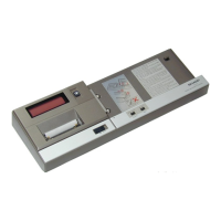
Remove the
te
rminal cover located on the left side panel
of
Ute pocket computer and place t
he
cover
in
th
e termin
al
cover reserve slot l
oc
ated
on
the back panel
of
the CE-I SO for future. use.
Fig. l
Term
in
al
cover
Hold
the
te
rmi
na
l
cover
he
re
0 •
·t
~
.
0
a
-=n
Cl
•
0
I~
3 I
(3)
Eng
ag
e studs on the CE-150 into the stud holes in the pocket computer as shown
by
arrow-
heads in order
of
number indicated and the procedure introduced next.
Fig. 2
Tr
iangle
mark
I)
Place the PC
-1
500 on the
CE-1
50 so t
hat
t
he
triangle mark should be
at
the left edge
of
the
PC-1500.
To
the bottom
1
I I
~
1
To
the le
ft
~\//
/
I t
~
~
\
~I
.
==::
=::::;;::·
:::=
==
M-Jlj~=:;=::;==
=
=='==
==:
=:::==
t-
--
Match surface
s:
t-
..
........,_
straight, otherwise,
'"=
======'
=£=~
==
'1-
!r
I
~
I
··-·
-·
---
pr
oper
connect;
on
,
...
:.
x
is
not
poss
ible,
<
To the front
Tri@nglt;t
m-@
rk
2)
If the point
2)
of
Fig
. 2 does not fit well, lightly
move
the pocket computer to left and right.
3)
After the point 2) fits, insert the point 3)(connection terminal) next.
•
Make
su
re
connect
or
pins. are firmly engaged and avoid
for
ce
ful
insertion.
Do not sale this PDF
!!
!