– 15 –
CD-K7000V,CP-C7000
CD SECTION
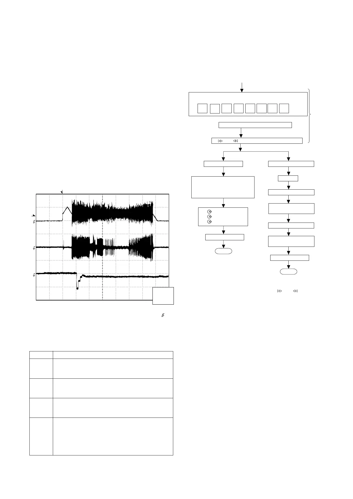
Figure 15
CD ERROR CODE DESCRIPTION
Error
State Code
[Servo System Error]
0001 Cannot detect Pickup-in SW
0002 DSP access error
[Error during close operation]
0101 Open/Close SW not functioning (Low → High)
0103 Open/Close SW not functioning (High → Low)
[Error during open operation]
0201 Open/Close SW not functioning (Low → High)
0203 Open/Close SW not functioning (High → Low)
[Error during skip operation]
0302 Pickup-in SW is not detected
0306 During Disc 1 search, Open/Close SW or Clamp SW
or Disc SW do not change to low.
0307 Clamp SW not function (Low → High)
0308 Clamp SW not function (High → Low)
Since this CD system incorporates the following automatic
adjustment functions, readjustment is not needed when
replacing the pickup. Therefore, different PWBs and pickups
can be combined freely.
Each time a disc is changed, these adjustments are
performed automatically. Therefore, playback of each disc
can be performed under optimum conditions.
Items adjusted automatically
(1) Offset adjustment (The offset voltage between the head
amplifier output and the VREF reference voltage is
compensated inside the IC.)
* Focus offset adjustment
* Tracking offset adjustment
(2) Tracking balance adjustment (waveform drawing Fig. 15
EFBL)
(3) Gain adjustment (The gain is compensated inside the IC
so that the loop gain at the gain crossover frequency will
be 0 dB.)
* Focus gain adjustment
* Tracking gain adjustment
• Adjustment
T
T
EFBL
FDO
TE
Stopped
CH1=500mV
DC 10:1
CH2=200mV
DC 10:1
CH3=1V
DC 10:1
500ms/div
(500ms/div)
NORM:20kS/s
1
2
3
=Record Length=
Smoothing : ON CH1 : 0.000V
CH2 : 0.000V
Main : 100K
Zoom : 2k
Mode : SINGLE
Type : EDGE CH1
Delay : 0.0ns
Hold off : 0.2µs
CH3 : 0.00V
CH4 : 0.00V
BW : FULL
=Trigger==Filter= =Offset=
CH2
v/DIV
200mV
1999/04/05 20:26:47
TEST MODE
· Setting the test mode
Any one of test mode can be set by pressing several keys as
follows.
<X-BASS> + <CD> + <POWER> TEST:CD operation test
Function:-CD test mode.
-Enter test mode.
C D T E S T
OPEN/CLOSE operation is using manual.
<< >>, << >> buttons make pick's slide possible.
Do TOC IL. Do normal play
When these following key is input
into PLAY key, track number can
be appoint directly
<<PLAY>> key input.
<<MEMORY>> key input.
<< 1>> key: Track 4
<<
2>> key: Track 9
<<
3>> key: Track 15
<<STOP>> key input.
STOP
Laser ON.
<<MEMORY>> key input.
Tracking OFF play at that
specific point.
<<MEMORY>> key input.
Tracking ON play at that
specific point.
<<STOP>> key input.
STOP
IL isn't done
VOL — Last memory
BAL — CENTER
P.GEQ — FLAT
X-BASS — OFF
To cancel : Power OFF
Sliding the PICKUP with
<<
>>, << >> button
must only be in STOP mode.